Briggs High RPM Poor Boy Special

#41
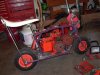
Rhovis likes your build!

Got a few pieces of advice for you to consider if you ever have it pulled down again

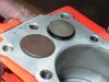
Radius to top of the cylinder over by the valves. Don't go very deep on the cylinder or you'll get into the ring travel. Over by the intake valve. That will help air flow fill the cylinder.

Mill the head as much as you can before things start hitting. The more compression the better.

If at all possible, try to grind the clearance you need into the cam. That rod needs a much strength as it can get. You did good checking for spring bind.

One last thing: you could knife edge the crank counter-weights to help cut through the oil but then you'll be looking at a balance job. Didn't notice if the wrist pin was tubular or solid but going to a hollow pin will allow you to cut and contour the crank weights a little and still be close on balance.

It wouldn't hurt anything to back cut and neck the valves a little to help with flow.

If you really wanted to get trick, you could also gas port the piston at the top ring or even file a small edge on the bottom of the piston skirt to help shave oil off the wall ?

We'll stop now...................you're doing just fine. Please continue and keep us advised
 
#42
Finally, I have an update! It took the place I bought the spring pocket cutter from, a long time to get it mailed, but it finally got here. It worked like a charm! It really is a very nice high quality tool. I no longer have any coil bind issues. You can see in the pic below that I had to cut the exhaust side deeper to get the required clearance. Minimum is supposed to be .050, but I set them at .060. The pockets also allowed me to get rid of the retainers I had installed to keep the spring centered on the valve. I set the valve clearance at IN .006, and EX .008. The cam called for .006 on both but the exhaust runs so much hotter, I felt more comfortable with a little more room for expansion, and I don't think .002 will hurt performance much.
I ran into one more snag with this build. The new billet lifters have a much larger radius where the stem of the lifter comes to the head, for added strength. With this cams lift, as it approached the top of the lobe, the radius of the lifter would run into the bottom of the lifter bore, and it wouldn't turn any further. This wasn't a very big deal as I have a 90 degree die grinder, and I used a conicle Carbide cutter to open the bottom of the lifter bores slightly for clearance. It would be nice if the cam companies would let you know the extent of the mods that are required for a cam, if for no other reason, to at least let the Do It Yourself guys know which ones not to pick!:laugh: In retrospect, it would have been easier, and more economical to have used the 94ss, but I'm still glad I used the 03ss. Bigger is always Better, Right?:laugh: :laugh:
I also decided to open the intake port side of the block into the cylinder, a little, as can be seen in the pics below.

Matt
 
#44
The Rhovis is pleased.
Yeah, I decided it couldn't hurt to have a little extra flow. As far as milling the head any further, I don't think it would be wise. If you set the head on the block without the gasket, when the valves open, they lift the head about .020 off of the block, but no contact once the gasket is installed. I know I stated in a previous post that the cam was hitting the rod, but it was actually the crankshaft contacting the intake lobe of the cam. The crank was already factory clearanced in this spot, so I just clearanced it a little more, and no more contact.:thumbsup: I appreciate the advice.:wink:

Matt
 
#47
Sorry I haven't updated in awhile, but I ran into a problem. I got the engine together, and started it up. I was really amazed at how well the Mikuni ran without any adjustment. It idled great, had great throttle response, and only had just a slight bog when you kicked it wide open rapidly. The engine sounded fantastic, but it smoked. I ran it for about an hour to see if it would stop, but it didn't, so I tore it back apart to inspect. Upon looking at the cylinder, I could see areas where it didn't look like the rings were making good contact with the cylinder. Most of the cylinder was shiny where the rings were contacting, but there were some areas where they weren't.:shrug: The cylinder appeared to be warped.
So, this is where I really ruin my budget!:censure: I bought a new .010 Raptor 3 piston off ebay for $28 shipped. Briggs Motorsports 5HP Piston Ring Kits 010 Raptor 3 Kart Racing L Head | eBay
I then dropped my block off at the machine shop to be bored ($30). It should be ready tomorrow. I'm sorry to everybody that was watching this quote "Poor Boy" build hoping to see great results for cheap, but you win some, and you loose some. In the mean time, I did paint the shroud to match the bike this is going on. http://www.oldminibikes.com/forum/project-logs/81117-roper-fun-build.html
I'll give an update very soon, and hopefully a video of the engine running.
 
#48
In your first assembly was the cylinder honed with a cross hatch ? In the pic above of what i can see of the cylinder there is no cross hatch . New rings and no cross hatch and it will burn oil .
 
#49
It had a beautiful cross hatch in it. I went back thru my pics to see if I could find a picture showing it, and I found one pic that you can see it a little, but that's the best one I could find. Thanks

Matt
 
#50
Got the engine back up and running today. It now has a .010 over piston, and No more smoke! I went ahead, and bolted it to the bike for a test run, and I love it. Its throttle response is good, but it does bog at wide open throttle, like its going lean, so its either going to need a larger jet, or it may need a fuel pump. I'll find out soon enough. I didn't let it wrap up very high, as I want to break it in first. With this clutches 3200 rpm engage, you better be hanging on when you goose it!:eek:hmy: Please forgive the terrible video. My camera takes good pics, but not video.:doah: I'll post further updates, as I get it tuned, and broke in. :thumbsup:

Matt

Sears Roper Mini Bike - YouTube
 
#56
The cylinder above started like this. That cylinder has been together for nearly 30 years in running condition, and was exercised several times annually.

Note the bevel at the top of the bore, next to the valves. L1050133.JPG L1050133.JPG L1050134.JPG
 
Top