Anything Goes! Build-from-scratch Dutch minibike 4.0
- Thread starter Li'l Popeye
- Start date
Building has start, finally...
This minibike will be a copy of my previous minibikes, except for some minor changes.
These changes have just been applied to the 3-D drawings of the minibike.
(Sorry, but measurements are in mm)
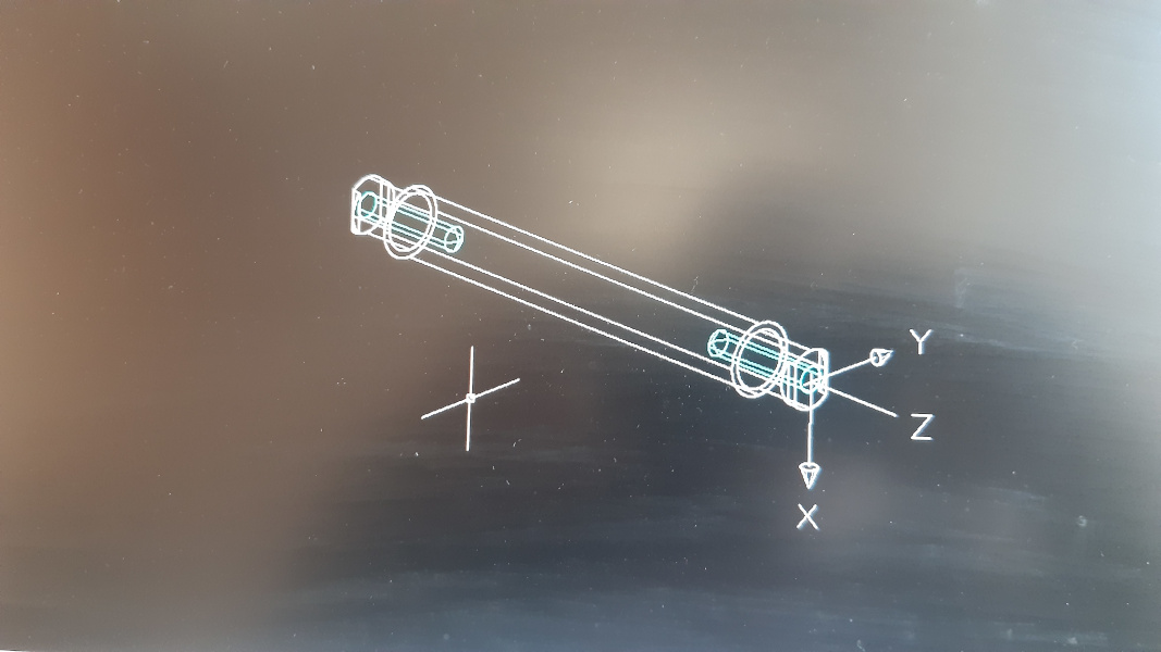
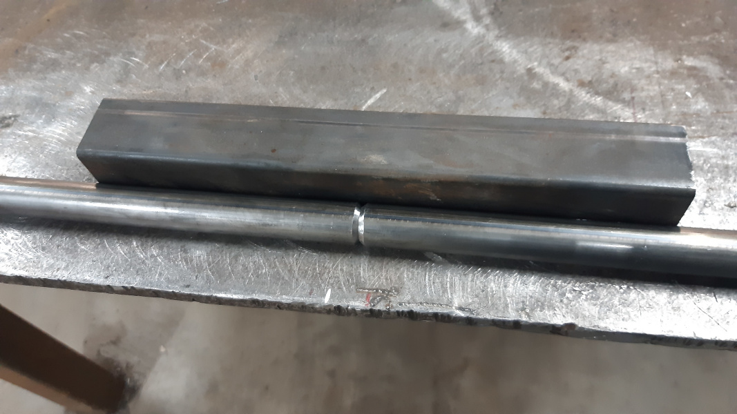
^This is the front- and rear axle of the previous minibikes. This was machined out of a solid round (25mm diameter) piece of steel. At both ends drilled and tapped holes, to accept M10 bolts. On both sides it accepted ball bearings with an inner diameter of 20mm.

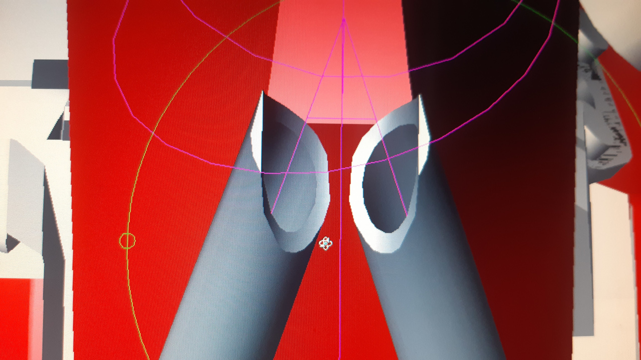
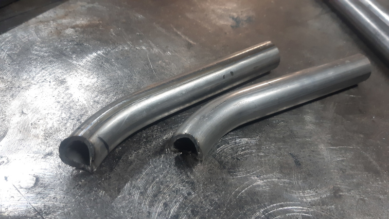
^The new minibike will be using a thick wall tube with outer diameter of 20mm. It is 10-11mm inside diameter.
Both ends will be machined to accept ball bearings with an inner diameter of 17mm. I'll keep the flat sides on both ends, they prevent the axle from turning and it works really well. A large M10 bolt will go through the axle to bolt it down to the frame. No more need to drill and tap holes.
^This is the rearaxle assembly. It's a machined 50mm diameter CrMo tube, with a sprocket adapter on 1 side, a brake disc adapter on the other side and a wheel adapter in the middle.
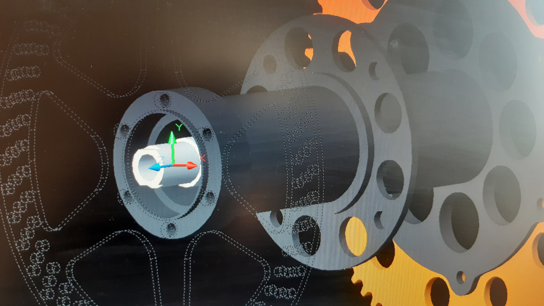
For the brake disc adapter I'll be using a thick wall tube (60mm outside, 39mm inside) this time. Because the new bearing (6203-2RS) has a different outer diameter, I had to redesign it.

^Redesigned brake disc adapter, ready to accept a smaller outer diameter bearing. I also added a groove for a circlip behind the bearing. Bearing is not visible, but I think you get the idea, where the bearing will be.
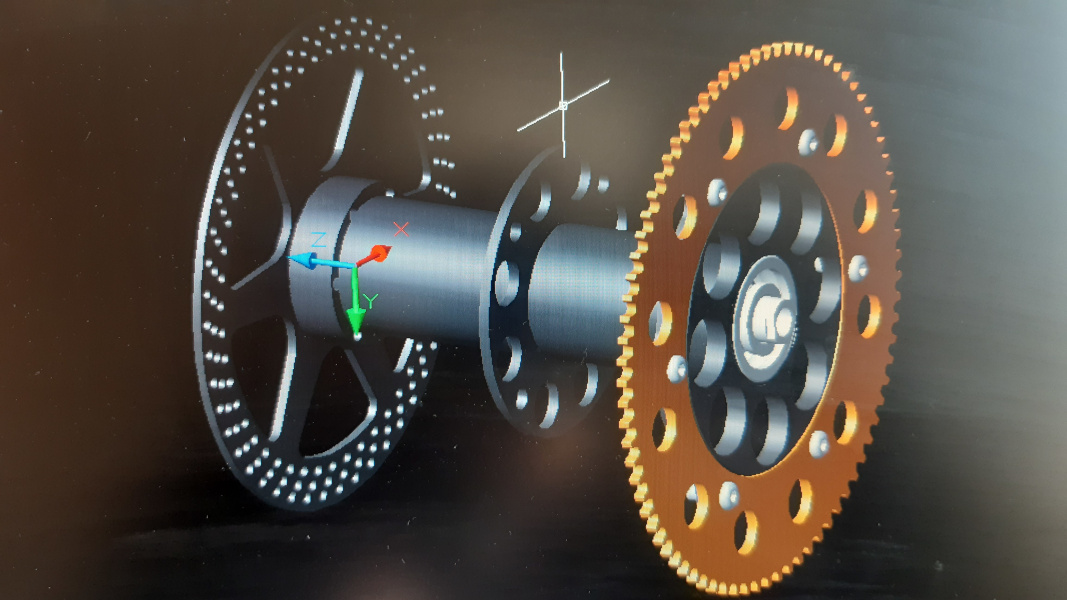
^No changes on the sprocket-side, as I was able to find a bearing (6303-2RS) with the same outer diameter and the smaller inner diameter.

^This is the design of my previous bikes. The parts where the axle is slide in, had been laser cut and machined on the mill. It was a bit time consuming and there's an easier way.

^I'll just use laser cut parts. No more milling. These will be placed 3mm more outside.

^Another lasercut part will be welded to it.
The flat sides of the shafts/axles will slide right into these. It prevents them from turning and it gives more "body" to keep it all in place.

^Backside view.
Another advantage, I forgot to mention, is that bolt heads of both sprocket and rotor have more clearance this way. No more, or at least, less grinding needed.
Time to start some tube bending...
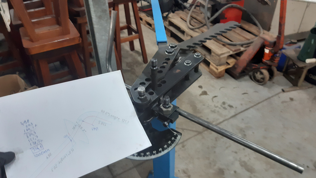
^I printed out drawings of the tube's centerlines and added the dimensions needed.
-I calculated the total length of the tube needed, added some extra length and cut them to that length.
-The length where the bents started was calculated and marked on the tube.
-The marks were all placed the same at the bending die. So length between bents should be okay.
-Over-length off tubes will be cut off later.

^Oops, something went wrong here. The marker lines are at the right spot, but 1 bent is on the wrong side of the marker line...
^We had to bent a new one, but ran out of tubing. So 2 smaller tubes were welded together.
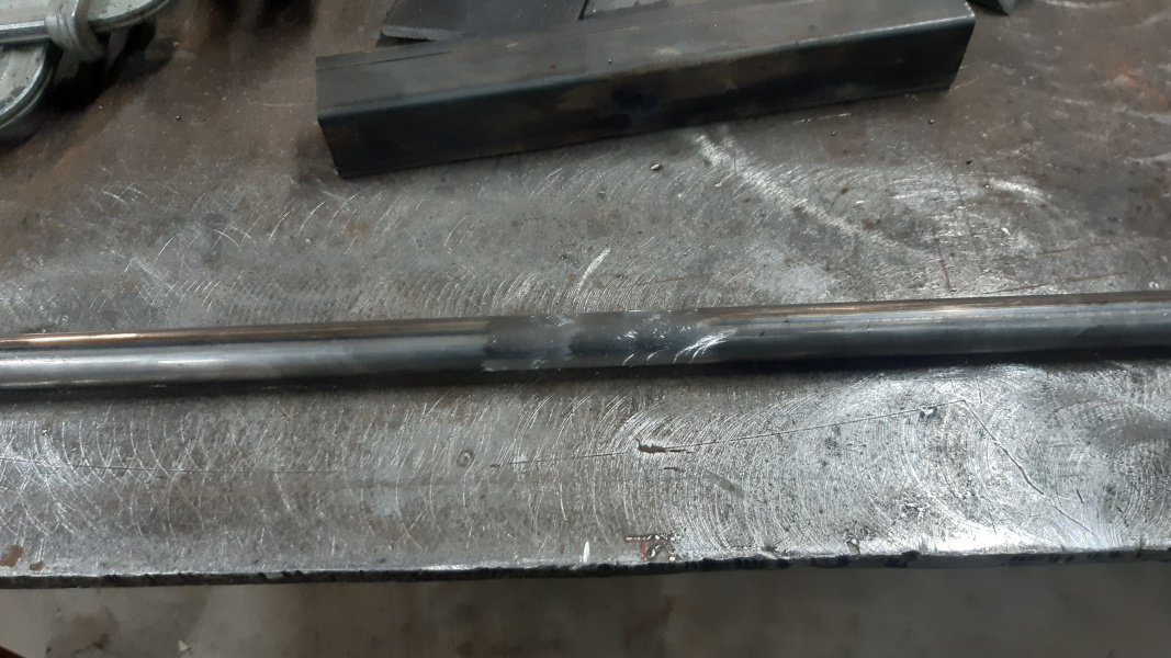
^No one will ever know, what happened here...

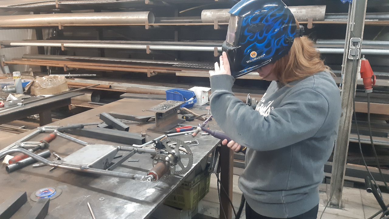
^My daughter operating the manual tube bender.

^All tubes (22x3mm) bent for the minibike frame. They still need to be cut to length. And some tube notching will have to take place.
That's it for now.
This minibike will be a copy of my previous minibikes, except for some minor changes.
These changes have just been applied to the 3-D drawings of the minibike.
(Sorry, but measurements are in mm)
^This is the front- and rear axle of the previous minibikes. This was machined out of a solid round (25mm diameter) piece of steel. At both ends drilled and tapped holes, to accept M10 bolts. On both sides it accepted ball bearings with an inner diameter of 20mm.
^The new minibike will be using a thick wall tube with outer diameter of 20mm. It is 10-11mm inside diameter.
Both ends will be machined to accept ball bearings with an inner diameter of 17mm. I'll keep the flat sides on both ends, they prevent the axle from turning and it works really well. A large M10 bolt will go through the axle to bolt it down to the frame. No more need to drill and tap holes.
^This is the rearaxle assembly. It's a machined 50mm diameter CrMo tube, with a sprocket adapter on 1 side, a brake disc adapter on the other side and a wheel adapter in the middle.
For the brake disc adapter I'll be using a thick wall tube (60mm outside, 39mm inside) this time. Because the new bearing (6203-2RS) has a different outer diameter, I had to redesign it.
^Redesigned brake disc adapter, ready to accept a smaller outer diameter bearing. I also added a groove for a circlip behind the bearing. Bearing is not visible, but I think you get the idea, where the bearing will be.
^No changes on the sprocket-side, as I was able to find a bearing (6303-2RS) with the same outer diameter and the smaller inner diameter.
^This is the design of my previous bikes. The parts where the axle is slide in, had been laser cut and machined on the mill. It was a bit time consuming and there's an easier way.
^I'll just use laser cut parts. No more milling. These will be placed 3mm more outside.
^Another lasercut part will be welded to it.
The flat sides of the shafts/axles will slide right into these. It prevents them from turning and it gives more "body" to keep it all in place.
^Backside view.
Another advantage, I forgot to mention, is that bolt heads of both sprocket and rotor have more clearance this way. No more, or at least, less grinding needed.
Time to start some tube bending...
^I printed out drawings of the tube's centerlines and added the dimensions needed.
-I calculated the total length of the tube needed, added some extra length and cut them to that length.
-The length where the bents started was calculated and marked on the tube.
-The marks were all placed the same at the bending die. So length between bents should be okay.
-Over-length off tubes will be cut off later.
^Oops, something went wrong here. The marker lines are at the right spot, but 1 bent is on the wrong side of the marker line...
^We had to bent a new one, but ran out of tubing. So 2 smaller tubes were welded together.
^No one will ever know, what happened here...
^My daughter operating the manual tube bender.
^All tubes (22x3mm) bent for the minibike frame. They still need to be cut to length. And some tube notching will have to take place.
That's it for now.
A lot of things have changed lately in this world... So did my plans.
Before continuing the minibike, I've decided to finally finish a side project; it's my road-legal, electric scooter. On good-weather days I use it to travel to work. It's almost done and minibike news below the "scooter pics".
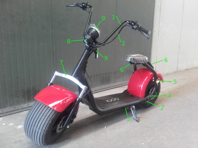
This is it, when I bought it a couple of years ago. I have numbered some things that I have customized.
1-Handle bar a bit to high.
2-Electric cables in plain sight or ziptied down to the frame; I re-route them inside the tubing, as far as possible.
3-A kick stand switch shuts the scooter off. I removed the switch; no more faults and cleaner look.
4-Frame tag plate in plain sight, I relocated the plate to a place out of sight.
5-Some mandatory, but ugly, round side reflectors; replaced them with reflectors which match the scooter a bit better.
6-License plate holder with square tubing; I removed the square tube under the seat and moved the licenseplate more forward (more out-of-sight).
7-This shiny part painted over in same color as rest of scooter.
8-Headlight, replaced it with a decent one, which actually lights up the road ahead.
9-Keyswitch and speedometer; relocated to a new dash I made.

Scooter parts ready for paint. I've painted it with 2-K spraycans. Color black, mat finish.
First time I used these spray cans (I never heard of it) and I might use them for future projects, too. The paint seems to have a high scratch resistance. (Video how 2-K spraycans work)

Relocating wires through frame tubes. I added rubber grommets, because a lot of wiring is 67,2 Volts.

Re-assembly of all parts and adding new wiring. I also added a Volt, Ampere meter in the dash, along with a USB charge port.
Making new wiring is more time consumable as I thought... I still need to replace some ugly, green colored bolts.
BACK TO MINIBIKE(S)...

...Yes, 2 sets of minibike tubing is bent. Does it mean that we're building 2 minibikes?! Yes, it does.
Fabricating a second minibike at the same time, is easier and quicker.
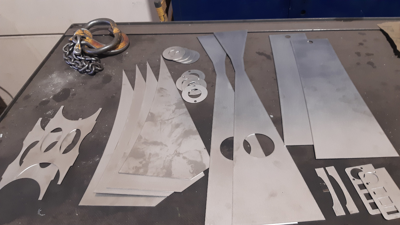
Stainless steel parts lasercut at work. Parts for fueltanks, exhausts, and battery holder.

Some steel lasercut parts, including 15T, #219 chain sprockets for torque converter. Some parts are missing in the picture, like: brake rotors and sheet metal to make fenders.
There's not much time left before the "build-off" ends, but we'll do our best to get it finished in time. After I finish my scooter...
It looks like all parts are gathered for 2 minibikes, except for some "aftermarket" engine parts. But a stock engine will work, too.
Stay healthy and stay tuned.
Before continuing the minibike, I've decided to finally finish a side project; it's my road-legal, electric scooter. On good-weather days I use it to travel to work. It's almost done and minibike news below the "scooter pics".
This is it, when I bought it a couple of years ago. I have numbered some things that I have customized.
1-Handle bar a bit to high.
2-Electric cables in plain sight or ziptied down to the frame; I re-route them inside the tubing, as far as possible.
3-A kick stand switch shuts the scooter off. I removed the switch; no more faults and cleaner look.
4-Frame tag plate in plain sight, I relocated the plate to a place out of sight.
5-Some mandatory, but ugly, round side reflectors; replaced them with reflectors which match the scooter a bit better.
6-License plate holder with square tubing; I removed the square tube under the seat and moved the licenseplate more forward (more out-of-sight).
7-This shiny part painted over in same color as rest of scooter.
8-Headlight, replaced it with a decent one, which actually lights up the road ahead.
9-Keyswitch and speedometer; relocated to a new dash I made.
Scooter parts ready for paint. I've painted it with 2-K spraycans. Color black, mat finish.
First time I used these spray cans (I never heard of it) and I might use them for future projects, too. The paint seems to have a high scratch resistance. (Video how 2-K spraycans work)
Relocating wires through frame tubes. I added rubber grommets, because a lot of wiring is 67,2 Volts.
Re-assembly of all parts and adding new wiring. I also added a Volt, Ampere meter in the dash, along with a USB charge port.
Making new wiring is more time consumable as I thought... I still need to replace some ugly, green colored bolts.
BACK TO MINIBIKE(S)...
...Yes, 2 sets of minibike tubing is bent. Does it mean that we're building 2 minibikes?! Yes, it does.
Fabricating a second minibike at the same time, is easier and quicker.
Stainless steel parts lasercut at work. Parts for fueltanks, exhausts, and battery holder.
Some steel lasercut parts, including 15T, #219 chain sprockets for torque converter. Some parts are missing in the picture, like: brake rotors and sheet metal to make fenders.
There's not much time left before the "build-off" ends, but we'll do our best to get it finished in time. After I finish my scooter...
It looks like all parts are gathered for 2 minibikes, except for some "aftermarket" engine parts. But a stock engine will work, too.
Stay healthy and stay tuned.
Electric scooter is finished and today we started working on the minibike again.

^Finished electric scooter. The dash shows the numbers while doing a "burnout". 31km/hr, 53.5 Volts and 29.2 Amperes (=1500/1600 Watts).
Minibike...
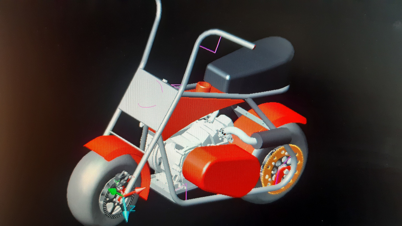
^This is what we're going to build.
Also in these colors. RAL colors 9023 (pearl dark grey) and RAL 3020 (traffic red). These were the colors we had on our modified pulling tractor "Popeye". Website of our pulling tractor.
The minibike will be called: "Li'l Popeye".
Tubes were bent about 3 weeks ago; today we started to cut some of them to length, as they have been bent with overlength.

^Measurements are taken of the drawings. This drawing is of a side frame rail.
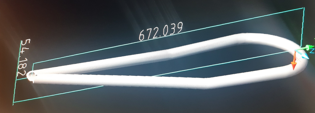
^This drawing is of the top frame rail.

^This is the top frame rail, cut to length, but needs to be cut in the neck to get it more narrow.

^The top frame rail after it is made more narrow.

^Clamp it all down and level before welding.

^Drawing of a fork tubes. Left one. With length of where to cut.
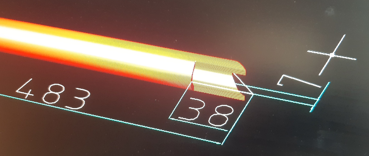
^Also measurements of yet-to-be-milled-down-part where front axle plate/holder will be welded.

^All fork tubes cut to the right length.
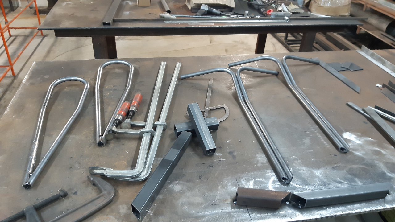
^This parts are ready for further assembly.
More parts to follow this weekend.
Stay tuned.
^Finished electric scooter. The dash shows the numbers while doing a "burnout". 31km/hr, 53.5 Volts and 29.2 Amperes (=1500/1600 Watts).
Minibike...
^This is what we're going to build.
Also in these colors. RAL colors 9023 (pearl dark grey) and RAL 3020 (traffic red). These were the colors we had on our modified pulling tractor "Popeye". Website of our pulling tractor.
The minibike will be called: "Li'l Popeye".
Tubes were bent about 3 weeks ago; today we started to cut some of them to length, as they have been bent with overlength.
^Measurements are taken of the drawings. This drawing is of a side frame rail.
^This drawing is of the top frame rail.
^This is the top frame rail, cut to length, but needs to be cut in the neck to get it more narrow.
^The top frame rail after it is made more narrow.
^Clamp it all down and level before welding.
^Drawing of a fork tubes. Left one. With length of where to cut.
^Also measurements of yet-to-be-milled-down-part where front axle plate/holder will be welded.
^All fork tubes cut to the right length.
^This parts are ready for further assembly.
More parts to follow this weekend.
Stay tuned.
Some pictures with text of the latest developments:
^This is the neck tube; some collars have been welded to it, these collars is where the ball bearings will fit in.

^Making it look clean with the help of the lathe.
^Looks like it's made out of a 1 piece of steel.
^Because we're building 2 minibikes; 2 necktubes, 2 neck axles, 2 frontaxles and 2 rearaxles, as I have planned on making them.
I considered it was not going to function, because the hole is to big. It will have some play between the bolt and the axle and that's not what I want...
^...So, back to the original plan; the axles are now made out of solid steel round bar. Pictured with the milled down flat sides, which will prevent the axles from turning. The blind holes will be (by now; have been) tapped with M10 regular thread.
^This is how the frame tubes need to be notched to fit the neck.

^A printed out template of a tube notching calculator, wrapped around a tube to mark, how to grind the tube. For the other side, the same paper was used except backwards.

^With a grinder the tube is notched. And checked for fitment and grinded some more and checked again and grinded and checked...untill it fit.
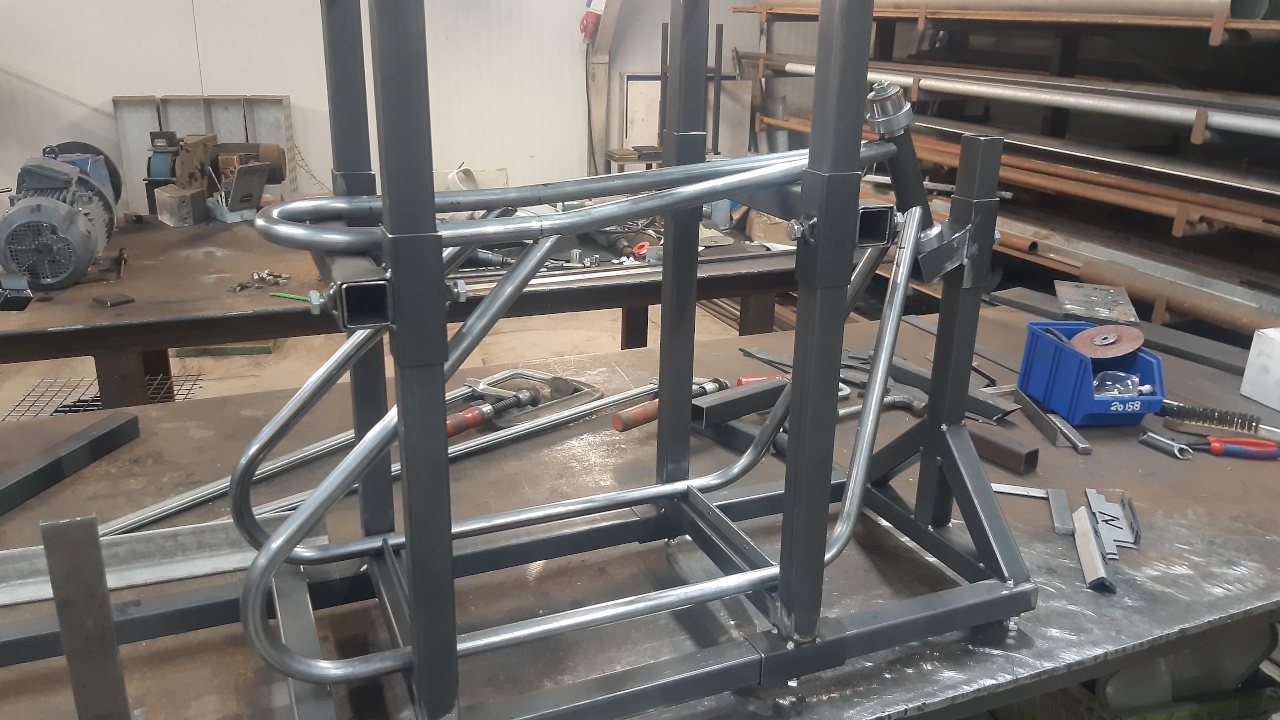
^Some frame parts in the welding jig, checking to see if all measurements are same as in the drawings.

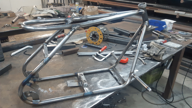
^It's starting to look like a minibike.
Still a lot more to do.
Stay tuned.
^This is the neck tube; some collars have been welded to it, these collars is where the ball bearings will fit in.
^Making it look clean with the help of the lathe.
^Looks like it's made out of a 1 piece of steel.
^Because we're building 2 minibikes; 2 necktubes, 2 neck axles, 2 frontaxles and 2 rearaxles, as I have planned on making them.
I considered it was not going to function, because the hole is to big. It will have some play between the bolt and the axle and that's not what I want...
^...So, back to the original plan; the axles are now made out of solid steel round bar. Pictured with the milled down flat sides, which will prevent the axles from turning. The blind holes will be (by now; have been) tapped with M10 regular thread.
^This is how the frame tubes need to be notched to fit the neck.
^A printed out template of a tube notching calculator, wrapped around a tube to mark, how to grind the tube. For the other side, the same paper was used except backwards.
^With a grinder the tube is notched. And checked for fitment and grinded some more and checked again and grinded and checked...untill it fit.
^Some frame parts in the welding jig, checking to see if all measurements are same as in the drawings.
^It's starting to look like a minibike.
Still a lot more to do.
Stay tuned.
Today I have machined brake rotor adapters.
^These adapters will be welded to a tube and together with a wheel adapterplate it is the front axle assembly. For the rear axle assembly there's an additional sprocket adapter welded to the tube. A ball bearing will fit inside the rotor adapter.

^Drilling holes which will need to be tapped, yet.

^The lasercut rotor fits perfectly.
Stay tuned.
^These adapters will be welded to a tube and together with a wheel adapterplate it is the front axle assembly. For the rear axle assembly there's an additional sprocket adapter welded to the tube. A ball bearing will fit inside the rotor adapter.
^Drilling holes which will need to be tapped, yet.
^The lasercut rotor fits perfectly.
Stay tuned.
Before we continue with welding the frame, we need the aluminium engine mounting plate. We'll bolt it onto the steel supports, before we weld the supports to the frame. This is easier and more accurate as measuring, where the supports need to be welded.
I have started the fabrication of the aluminium engine plate and hope we can start welding this weekend.
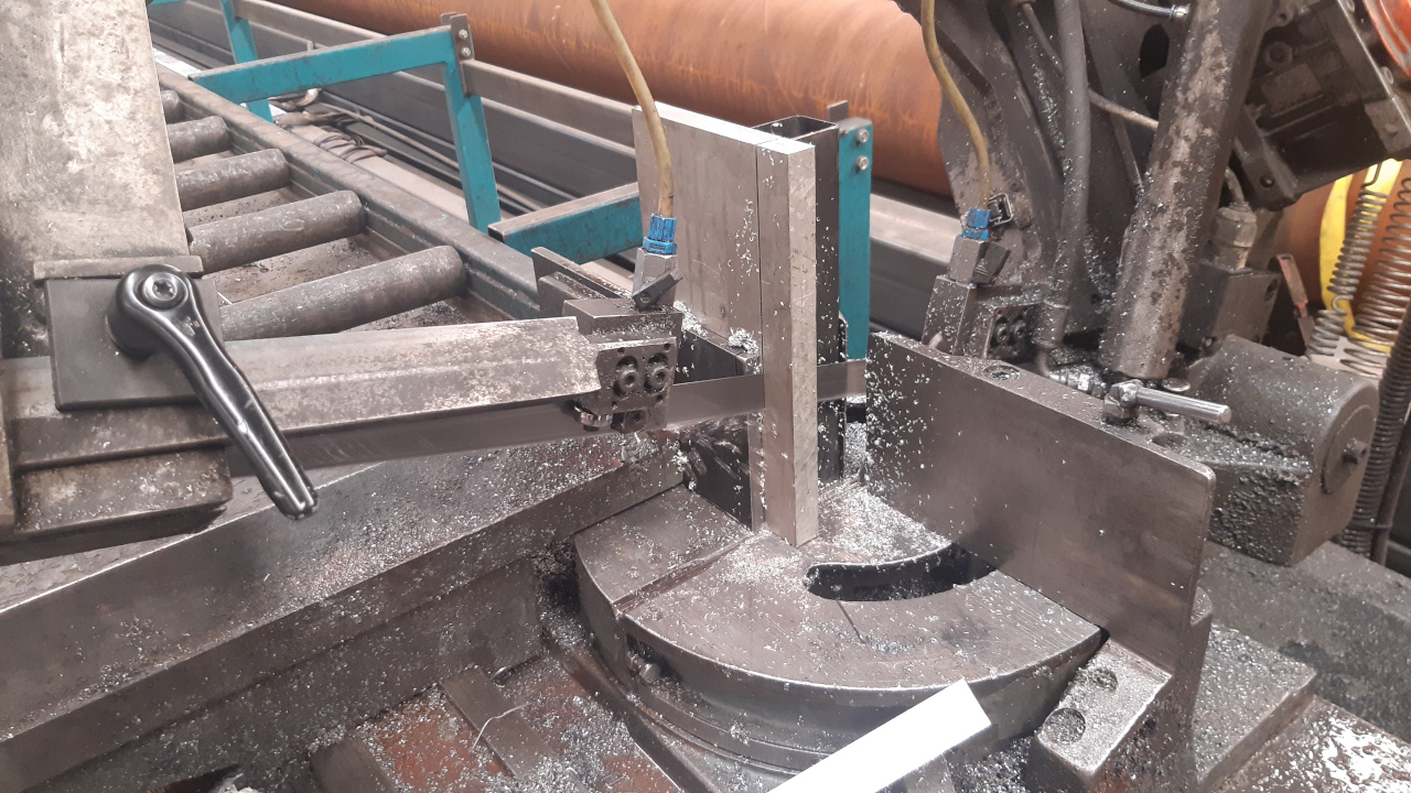
^Cutting a piece of aluminium with a saw. 20mm thick; no flex in this engine plate...

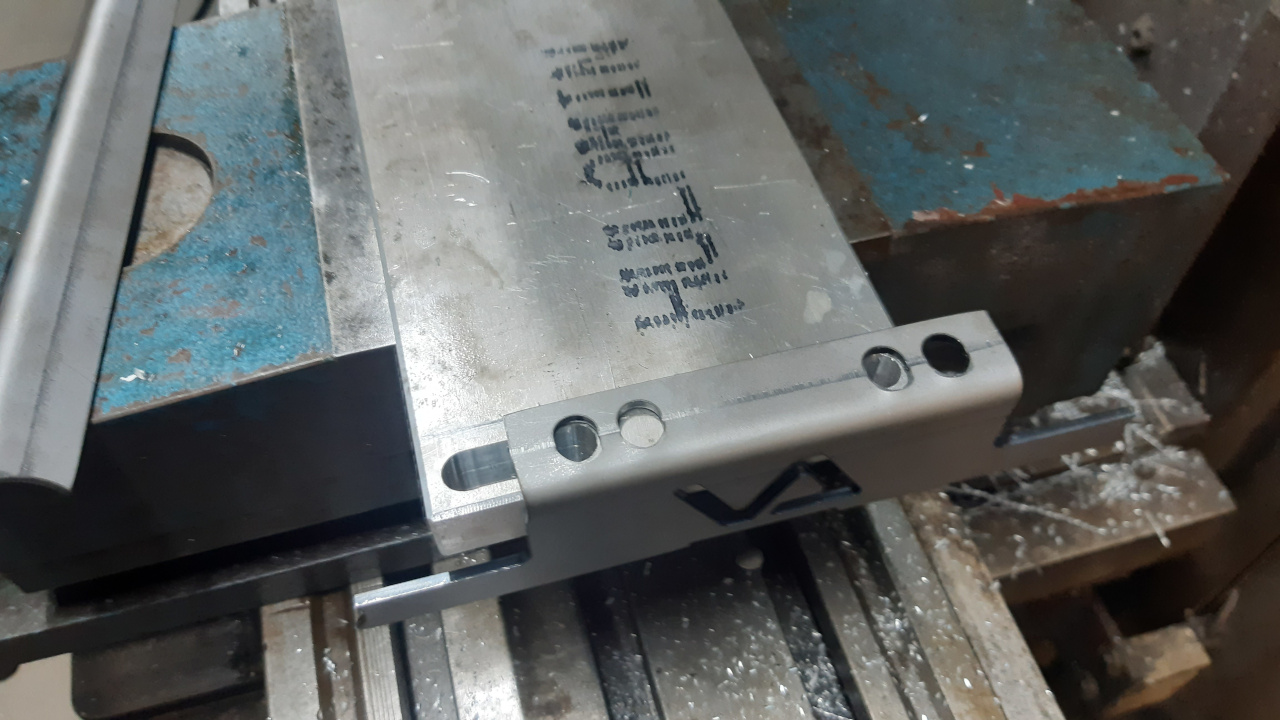
^This is what it is going to look like. Slot holes for adjustment sideways and slotholes to adjust chain tension. Measurements are in mm and perfect fit for GX160 engine.

^Most right position...
^...Most left position.
I have started the fabrication of the aluminium engine plate and hope we can start welding this weekend.
^Cutting a piece of aluminium with a saw. 20mm thick; no flex in this engine plate...
^This is what it is going to look like. Slot holes for adjustment sideways and slotholes to adjust chain tension. Measurements are in mm and perfect fit for GX160 engine.
^Most right position...
^...Most left position.
I sure envy your machinist skills & never knew I wanted to have the skills myself until I found this hobby in 2015. I can dream up what I think is some killer ideas, I'm just unfortunately limited as to what I can do.
Anyhow love your work & thanks for sharing.
You sure set the bar high!
Anyhow love your work & thanks for sharing.
You sure set the bar high!
It might be over the top, but I prefer to do it this way, while there might be easier ways to make something.
This way is not good if your building a minibike, which you want to sell. No one will ever pay the money it's worth to me.
Today I've finished both aluminium engine plates. I need just one for the minibike in this build off, but wheile I was at it, I made another one for the other, yet-to-build, minibike.
^This is about 3-4 hours of work on the Bridgeport mill. Now the engine plate is ready, we can continue with assembling the frame.
I also need to do a bit of milling at the fork tubes, before we start welding the front fork together. With a weekend coming up, things can get going.
For this build a lot of video is captured, which will be used for future video's at my youtube channel. First we'll try to finish the build before the deadline.
Stay tuned.
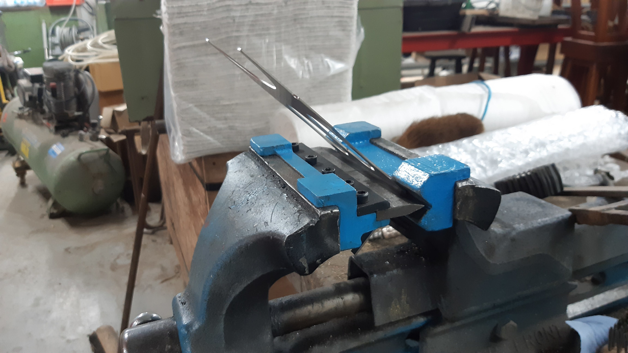
Today I went to the doctor, because of a "groin rupture", causing a lot of pain. After that I had some time left to mill the fork tubes.

^A fork tube milled down. This is where the front axle mounting plate will be welded.
Let's hope I can get a bit more done this weekend as I did today.
Stay tuned.
^A fork tube milled down. This is where the front axle mounting plate will be welded.
Let's hope I can get a bit more done this weekend as I did today.
Stay tuned.
^The rearaxle is spinning faster as it will ever do (nothing welded, yet).
This afternoon I've spent with making parts for front- and rear axle assemblies. They will all be tack welded together, soon.
These are needed to be able to weld the brake caliper mounts to the frame and fork.
What's next?!:
Finish front and rear axles.
Tack and weld the frame and fork
Weld the mounts and supports to the frame
Make a stainless gastank.
Make a pair of fenders.
Seat.
Engine is not done, yet.
etc.

Great work, mad skills , you are in a league of your own!
Today I've spend some more time finishing the front and rear axle assemblies.
^First I welded the wheel- and rotor adapters to the chrome moly tube.
^Then machined the wheel adapters, in a way that the wheel is always centered to the adapter/axle and spinning true.
^After that the sprocket adapters were welded on and also machined these to make the sprocket center perfect and spinning true.
Most of the machining is done by now, finally.
I hope to be able to paint in the weekend following to Ascension Day, we have a 4 days weekend then.
I will have to order some more parts and order paint.
^This is the tractor "Popeye" we used to go tractorpulling, untill we stopped in 2012. This colorscheme is what I want on this build-off minibike: Li'l Popeye.
Today we started tacking the frame, fork and several supports/mounts together.
I hope you like pictures, because here are some of today's work:

^Frontfork tacked together. Axle bolted in place and some pieces of metal to keep the correct distance between the axle and the fender support, before tacking the fender support to the front fork.

^Welded. This is all that'll be welded of this plate. It's welded inside and outside and it needs no more welding. It will be stuffed with kit, once it gets painted.

^I've made these little supports on a press and weld them, there where I need them, to ziptie cables down to the frame or fork.
^My daugther thinking where to tack the caliper mount first. For it's position, we first mounted the axle, rotor and caliper.

^Tacked and now welding.
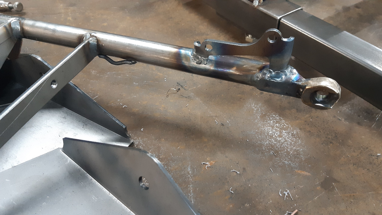
^Caliper mount welded. All the other parts also welded. Tig and mig go hand in hand.
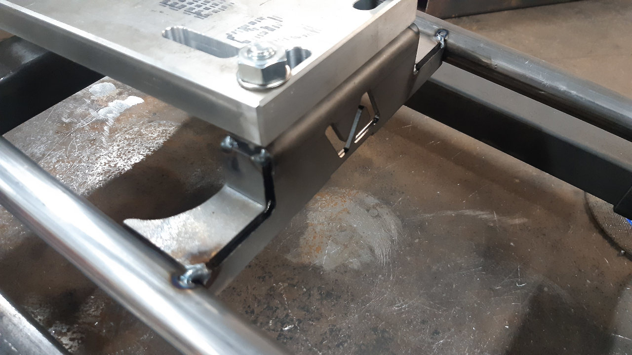
^The new machined engine plate bolted to the engine supports, to position them. This is the (raised for torque converter) rear engine support...
^...This is the lower front engine support. All perfect fit lasercut parts.

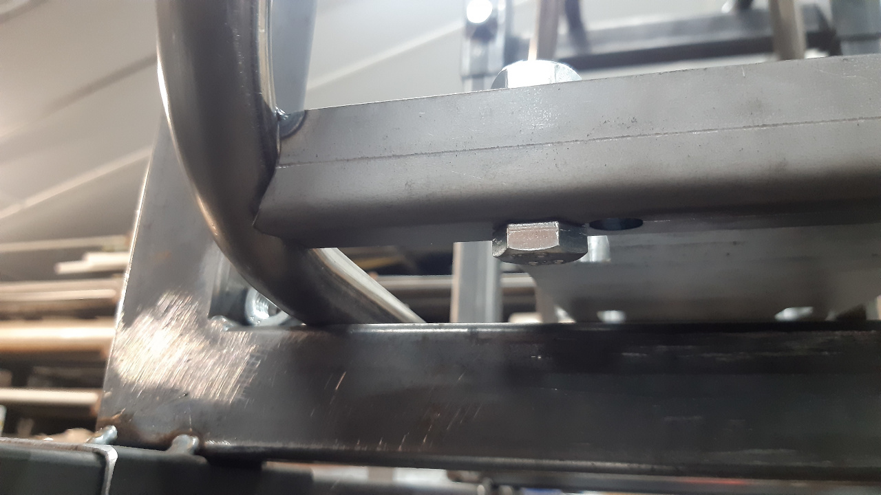
^Using nuts to position the rear axle, before tacking.

^These are the same pieces of metal as in the first picture. Here being used to distance the rear fender mount from the rear axle. The other piece of metal behind the axle is just temporarily there to keep the correct distance between the frame rails.

^Anti rotating plates welded in position.

^Ready to be taken out of the frame jig to weld everything.

^Almost forgot this support. It supports the rear fender at the bottom.
Tomorrow welding frame, and start with making fenders and/or gastank.
Paint has arrived last week and tires should be on their way.
I hope you like pictures, because here are some of today's work:
^Frontfork tacked together. Axle bolted in place and some pieces of metal to keep the correct distance between the axle and the fender support, before tacking the fender support to the front fork.
^Welded. This is all that'll be welded of this plate. It's welded inside and outside and it needs no more welding. It will be stuffed with kit, once it gets painted.
^I've made these little supports on a press and weld them, there where I need them, to ziptie cables down to the frame or fork.
^My daugther thinking where to tack the caliper mount first. For it's position, we first mounted the axle, rotor and caliper.
^Tacked and now welding.
^Caliper mount welded. All the other parts also welded. Tig and mig go hand in hand.
^The new machined engine plate bolted to the engine supports, to position them. This is the (raised for torque converter) rear engine support...
^...This is the lower front engine support. All perfect fit lasercut parts.
^Using nuts to position the rear axle, before tacking.
^These are the same pieces of metal as in the first picture. Here being used to distance the rear fender mount from the rear axle. The other piece of metal behind the axle is just temporarily there to keep the correct distance between the frame rails.
^Anti rotating plates welded in position.
^Ready to be taken out of the frame jig to weld everything.
^Almost forgot this support. It supports the rear fender at the bottom.
Tomorrow welding frame, and start with making fenders and/or gastank.
Paint has arrived last week and tires should be on their way.
This afternoon I have welded the frame, added the rear caliper mount and footpegs.

^After welding "straightening" frame with a torch. It became to narrow at the rearaxle section after welding and cooling down. A little heat on the opposite side of the weld will get it straight again.

^Mounted the rearaxle assembly, for positioning the caliper with mount.

^Caliper with mount.

^The mount bolted to caliper and located them on the rotor. The orange wire is there to have some (up/down) clearance between the rotor and caliper. The vise grip is functioning as a counterweight.
I wanted to start with making a gastank, but I almost forgot the footpegs. So I made some footpegs out of a piece of tube that was bent incorrect.

^I cut the bent at a 40 degree angle.
^Tubes notched with a grinder.

^Positioning the footpegs. They are at the same height as the wheel axles are.

^Footpegs welded to the frame and welded a bolt to them, to close them. The thread will be cut of.
^A frame almost done. It still needs supports for gastank and seat, which I will have to make first.

^The new seat as it comes. It is a buddyseat of a Puch moped. I can't use the mount...
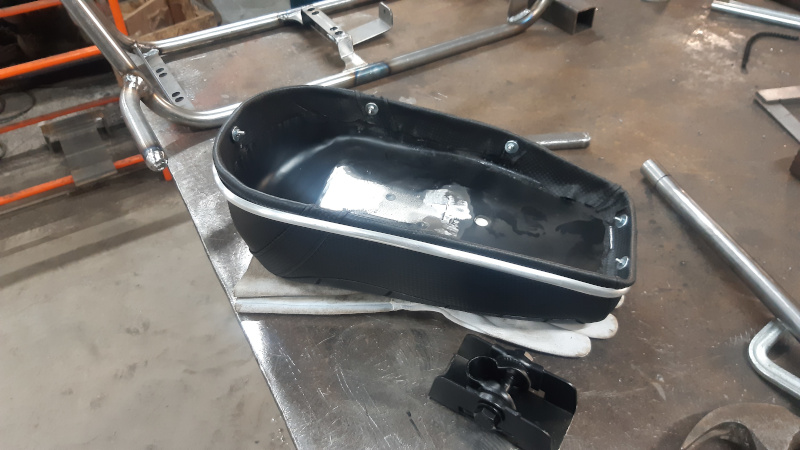
^...So I cut the mount off and will put 4 blind rivet nuts in it, tomorrow.

^I have cut a piece of tube for lengthening the filler neck. This will get the gas cap above the frame rails, which makes it easy to open.
Seat, gas tank and fenders are the only things to finish in order to have the frame ready for paint. There are other parts that need to be painted, too. Like exhaust, intake and other small things. They still need to be made, too. It will keep me busy this short week, besides work.
^After welding "straightening" frame with a torch. It became to narrow at the rearaxle section after welding and cooling down. A little heat on the opposite side of the weld will get it straight again.
^Mounted the rearaxle assembly, for positioning the caliper with mount.
^Caliper with mount.
^The mount bolted to caliper and located them on the rotor. The orange wire is there to have some (up/down) clearance between the rotor and caliper. The vise grip is functioning as a counterweight.
I wanted to start with making a gastank, but I almost forgot the footpegs. So I made some footpegs out of a piece of tube that was bent incorrect.
^I cut the bent at a 40 degree angle.
^Tubes notched with a grinder.
^Positioning the footpegs. They are at the same height as the wheel axles are.
^Footpegs welded to the frame and welded a bolt to them, to close them. The thread will be cut of.
^A frame almost done. It still needs supports for gastank and seat, which I will have to make first.
^The new seat as it comes. It is a buddyseat of a Puch moped. I can't use the mount...
^...So I cut the mount off and will put 4 blind rivet nuts in it, tomorrow.
^I have cut a piece of tube for lengthening the filler neck. This will get the gas cap above the frame rails, which makes it easy to open.
Seat, gas tank and fenders are the only things to finish in order to have the frame ready for paint. There are other parts that need to be painted, too. Like exhaust, intake and other small things. They still need to be made, too. It will keep me busy this short week, besides work.
Yesterday I have welded the seat bracket to the frame and tacked the gastank parts together.
^Bending sheetmetal for the batterybracket, which will be located under the seat.
^Battery bracket welded to the seat bracket and mounted to the seat. The batterybracket also has holes for some switches and for a XLR battery charger connector.

^Positioned the seat before welding the bracket to the frame. The flat pieces of metal are there to keep a nice gap between the seat and frame rails.

^New gastank; fillerneck welded to a piece of tube and tacked to the top plate of the gastank. A nut welded to the bottom plate of the gastank. This nut is where the fuel tap will screw in.

^Gastank parts tacked together.
The gastank will be welded before it is positioned in the frame, in order to tack the gastank brackets to the frame. That will be done tonight and I might also start with making the fenders.
Stay tuned.
^Bending sheetmetal for the batterybracket, which will be located under the seat.
^Battery bracket welded to the seat bracket and mounted to the seat. The batterybracket also has holes for some switches and for a XLR battery charger connector.
^Positioned the seat before welding the bracket to the frame. The flat pieces of metal are there to keep a nice gap between the seat and frame rails.
^New gastank; fillerneck welded to a piece of tube and tacked to the top plate of the gastank. A nut welded to the bottom plate of the gastank. This nut is where the fuel tap will screw in.
^Gastank parts tacked together.
The gastank will be welded before it is positioned in the frame, in order to tack the gastank brackets to the frame. That will be done tonight and I might also start with making the fenders.
Stay tuned.
I had planned to get started with making the fenders after I was done with the gastank, but it didn't get that far, yesterday evening.
Good news is that the gastank is welded and without any leaks in place.

^Here is the welded gastank being positioned, before tacking the brackets to the frame.

^Gastank in place and nice gaps all around.
Fenders are next on the checklist and perhaps I make it a roller first before I spray paint it. Just to confirm if it all fits.
Good news is that the gastank is welded and without any leaks in place.
^Here is the welded gastank being positioned, before tacking the brackets to the frame.
^Gastank in place and nice gaps all around.
Fenders are next on the checklist and perhaps I make it a roller first before I spray paint it. Just to confirm if it all fits.
Today I've worked on the minibike again, in order to get parts ready for spraypaint. I didn't make it a roller, as I didn't have wheels. I'm pretty sure everything fits.

^@13:46 PM. The sheetmetal parts for making my own fenders. In the back is a mold, which I use for tacking the sheetmetal parts together. These size fenders are nowhere to be found here in Netherlands, so I have to make them myself.

^@14:02 PM. First fender tacked.

^@14:17 PM. First fender welded. I have a piece of flat metal which is used to keep the distance, while welding and cooling down. Without this piece of metal, the fender gets out of shape and becomes to large. If it is to large it looks like crap on the minibike; the gap between the tire and the fender needs to be even all the way.

^@14:27 PM. While the first fender is cooling down, the second fender is being tacked.

@15:12 PM. Second fender welded and both fenders finished with a sanding- and flap disc. 1,5 hours to complete a pair of fenders.
Mounting holes have been drilled in the fenders and I started collecting parts that need to be painted. I will spray paint the parts at my home, not at the workshop. Temperature will be good to paint on Saturday and Sunday. Today (Thursday) and tomorrow it will be 82-86 degrees.

^The engine cover that came of the engine. There's rust on the inside and even some little holes, because of the rust. But I'll try to fix it, so I can use it. The dents need to go away, too.
Tomorrow another day to work on Li'l Popeye minibike: Get engine cover ready for paint, do some engine work and maybe start with intake and exhaust.
Stay tuned.
^@13:46 PM. The sheetmetal parts for making my own fenders. In the back is a mold, which I use for tacking the sheetmetal parts together. These size fenders are nowhere to be found here in Netherlands, so I have to make them myself.
^@14:02 PM. First fender tacked.
^@14:17 PM. First fender welded. I have a piece of flat metal which is used to keep the distance, while welding and cooling down. Without this piece of metal, the fender gets out of shape and becomes to large. If it is to large it looks like crap on the minibike; the gap between the tire and the fender needs to be even all the way.
^@14:27 PM. While the first fender is cooling down, the second fender is being tacked.
@15:12 PM. Second fender welded and both fenders finished with a sanding- and flap disc. 1,5 hours to complete a pair of fenders.
Mounting holes have been drilled in the fenders and I started collecting parts that need to be painted. I will spray paint the parts at my home, not at the workshop. Temperature will be good to paint on Saturday and Sunday. Today (Thursday) and tomorrow it will be 82-86 degrees.
^The engine cover that came of the engine. There's rust on the inside and even some little holes, because of the rust. But I'll try to fix it, so I can use it. The dents need to go away, too.
Tomorrow another day to work on Li'l Popeye minibike: Get engine cover ready for paint, do some engine work and maybe start with intake and exhaust.
Stay tuned.
Today's progress:

^This is 1 of 6 thumb throttles that I modified last year by installing a PTFE coated bushing in them and replacing the crappy shaft with a round stainless shaft. Today I have made a little adapter out of PVC, where I can screw in an adjustable cable thingy (don't know it's name).

^All installed and replaced Chinese green hardware with stainless hardware.

^This "lug" on the engine side cover needed to be milled down a bit, otherwise it will interfere with the backplate of the torque converter. I was planning on making billet oil plugs, but for now I will install the stock plugs.

^Engine side cover installed again and installed the cylinderhead, with 18 Lbs springs and a thin metal head gasket.
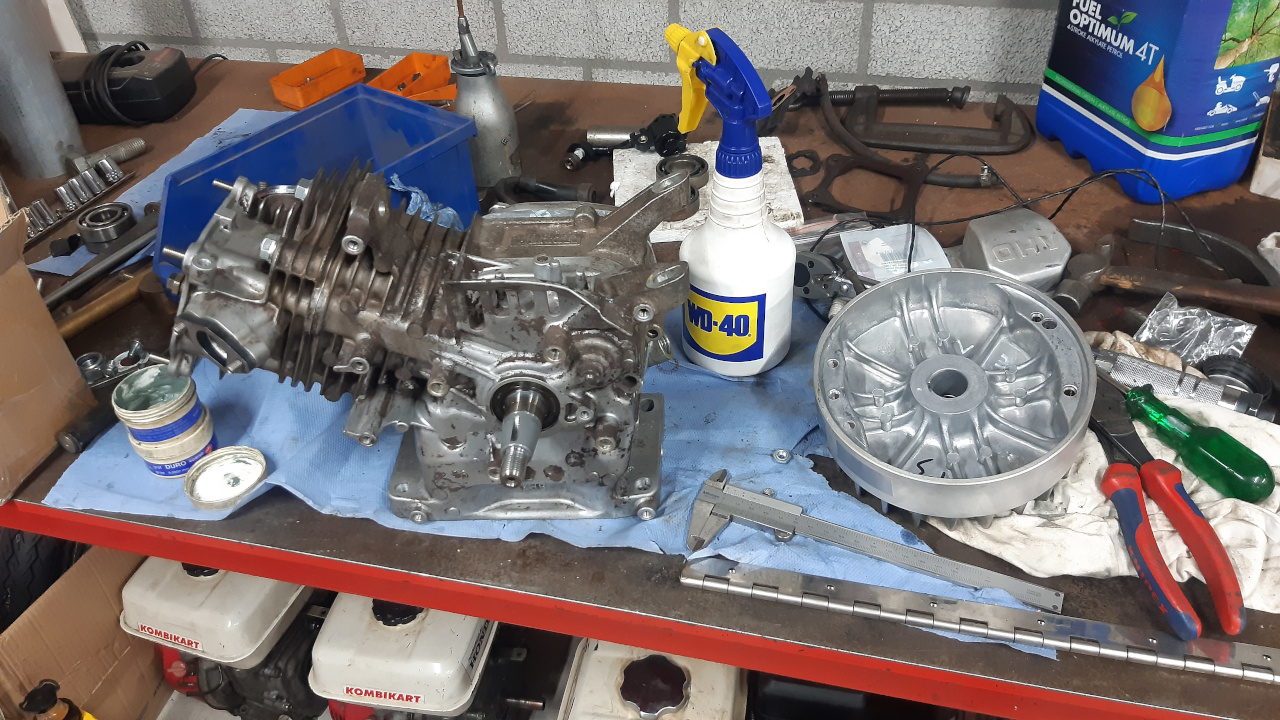
^Lapped the 3.3 lbs aluminium flywheel. Flywheel is part nr: 31110-Z1V-810. Under the workbench a couple of other GX160 engines, waiting for several future projects.
^This is 1 of 6 thumb throttles that I modified last year by installing a PTFE coated bushing in them and replacing the crappy shaft with a round stainless shaft. Today I have made a little adapter out of PVC, where I can screw in an adjustable cable thingy (don't know it's name).
^All installed and replaced Chinese green hardware with stainless hardware.
^This "lug" on the engine side cover needed to be milled down a bit, otherwise it will interfere with the backplate of the torque converter. I was planning on making billet oil plugs, but for now I will install the stock plugs.
^Engine side cover installed again and installed the cylinderhead, with 18 Lbs springs and a thin metal head gasket.
^Lapped the 3.3 lbs aluminium flywheel. Flywheel is part nr: 31110-Z1V-810. Under the workbench a couple of other GX160 engines, waiting for several future projects.
I got the parts painted today with spray cans.

^First a layer of 2-K epoxy primer.

^Adding kit at spots where water could get between parts, before spraying lacquer.
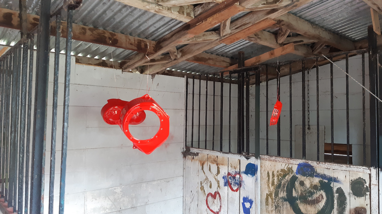
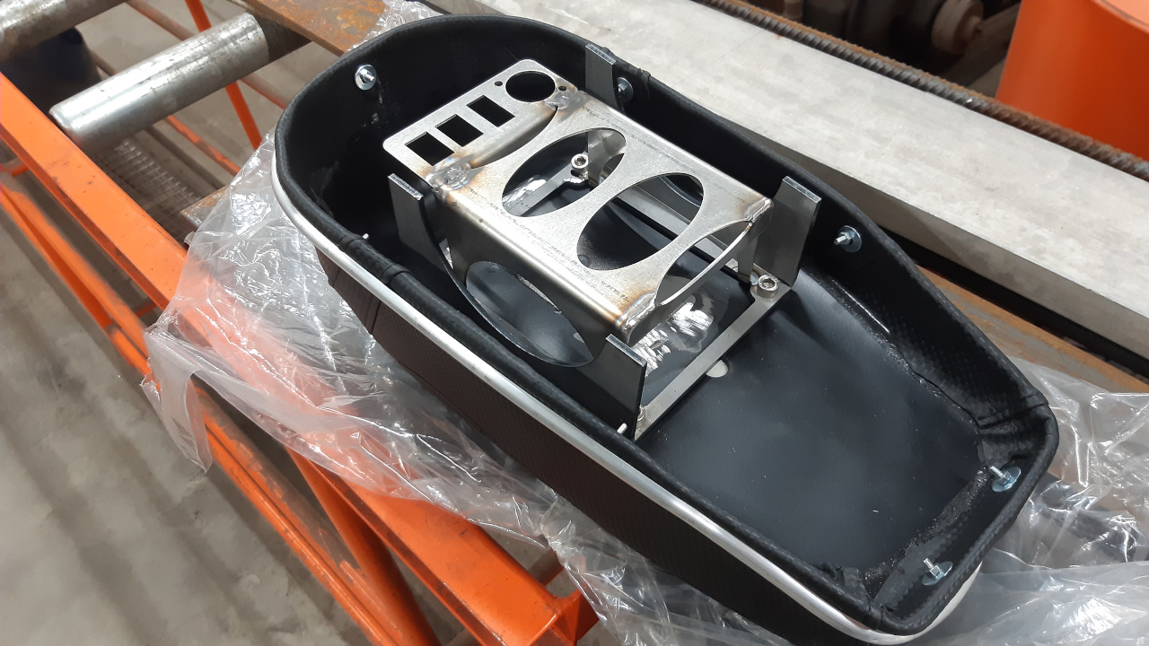
^These are some of the red parts (RAL3020), this is painted with 2-K spraypaint. I did not spray clearcoat over these. The torque converter cover is primered with plastic primer.
In the sun, this color looks a bit orange and if it is darker outside it seems much darker. It's a very bright red color.

^These are the parts that have been painted black with 2-K. Also no clearcoat over these.

^The frame and fork have been painted in 1-K "pearl dark grey", that is not available in 2-K, so 2 layers of 2-K clearcoat over it.

^Close up of the pearl dark grey color. RAL 9023.
The 2-K lacquer and 2-K clearcoat is said to be gasoline prove. If it is, I know I will be ordering this paint again.
Stay tuned.
^First a layer of 2-K epoxy primer.
^Adding kit at spots where water could get between parts, before spraying lacquer.
^These are some of the red parts (RAL3020), this is painted with 2-K spraypaint. I did not spray clearcoat over these. The torque converter cover is primered with plastic primer.
In the sun, this color looks a bit orange and if it is darker outside it seems much darker. It's a very bright red color.
^These are the parts that have been painted black with 2-K. Also no clearcoat over these.
^The frame and fork have been painted in 1-K "pearl dark grey", that is not available in 2-K, so 2 layers of 2-K clearcoat over it.
^Close up of the pearl dark grey color. RAL 9023.
The 2-K lacquer and 2-K clearcoat is said to be gasoline prove. If it is, I know I will be ordering this paint again.
Stay tuned.