Building a non hemi predator Test Motor

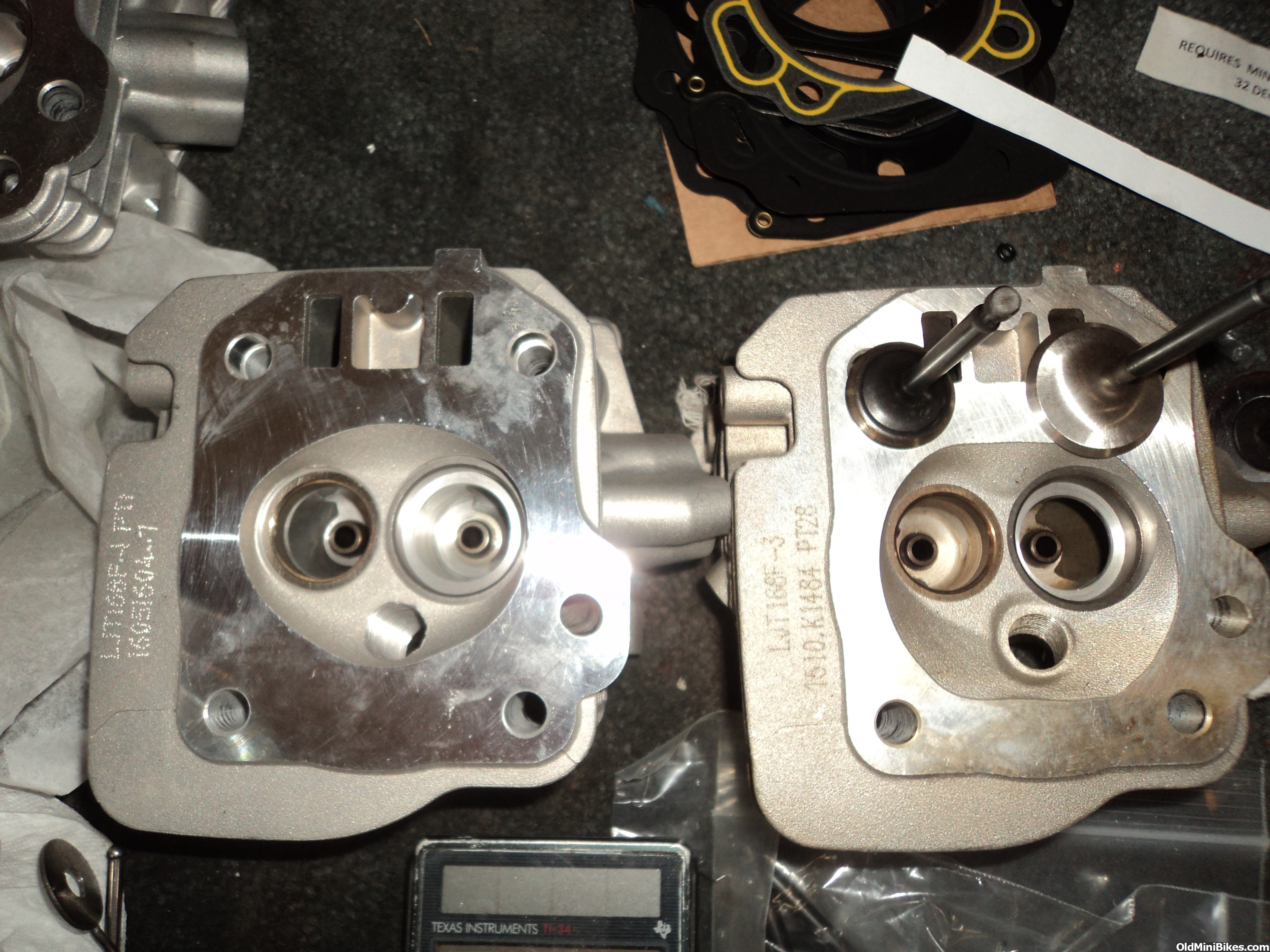

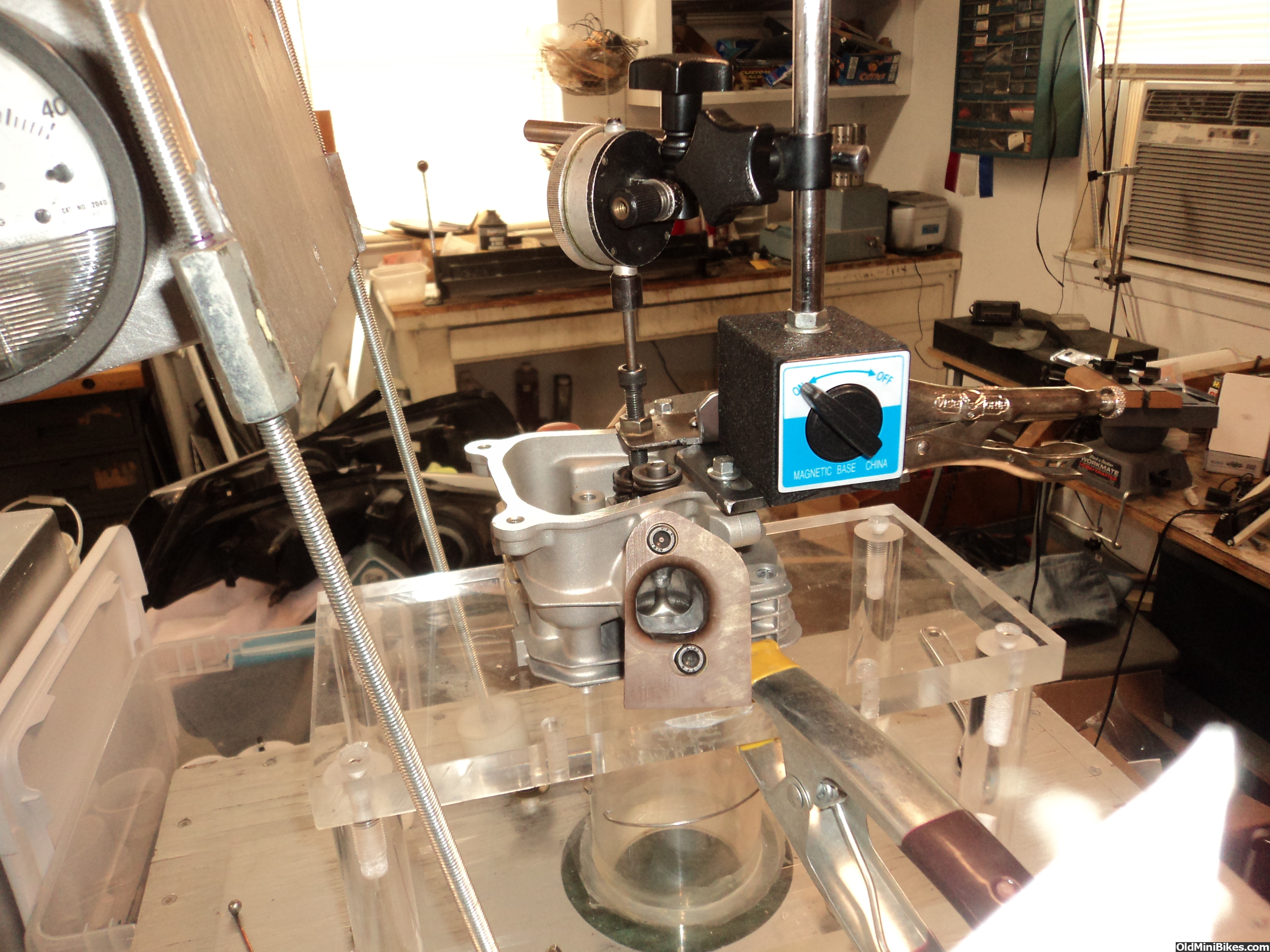
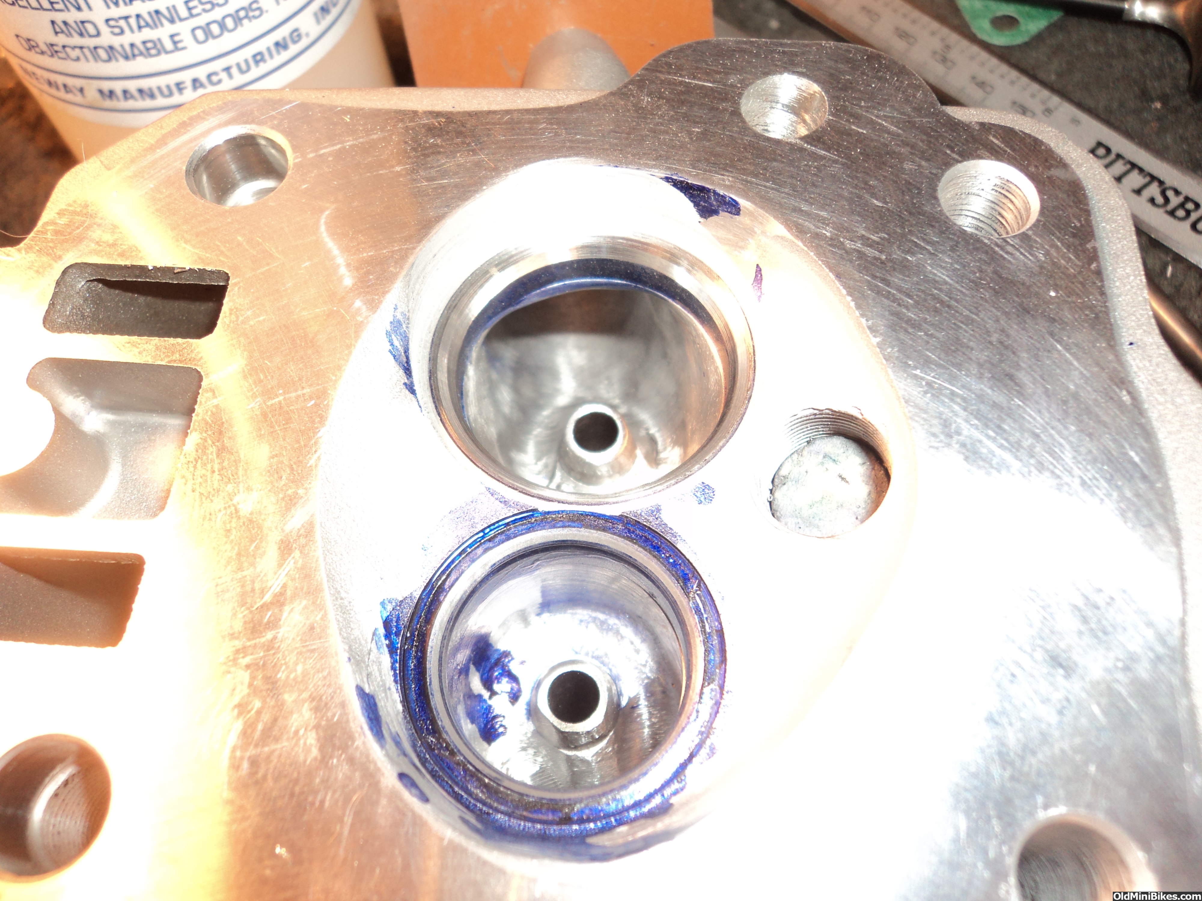
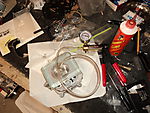
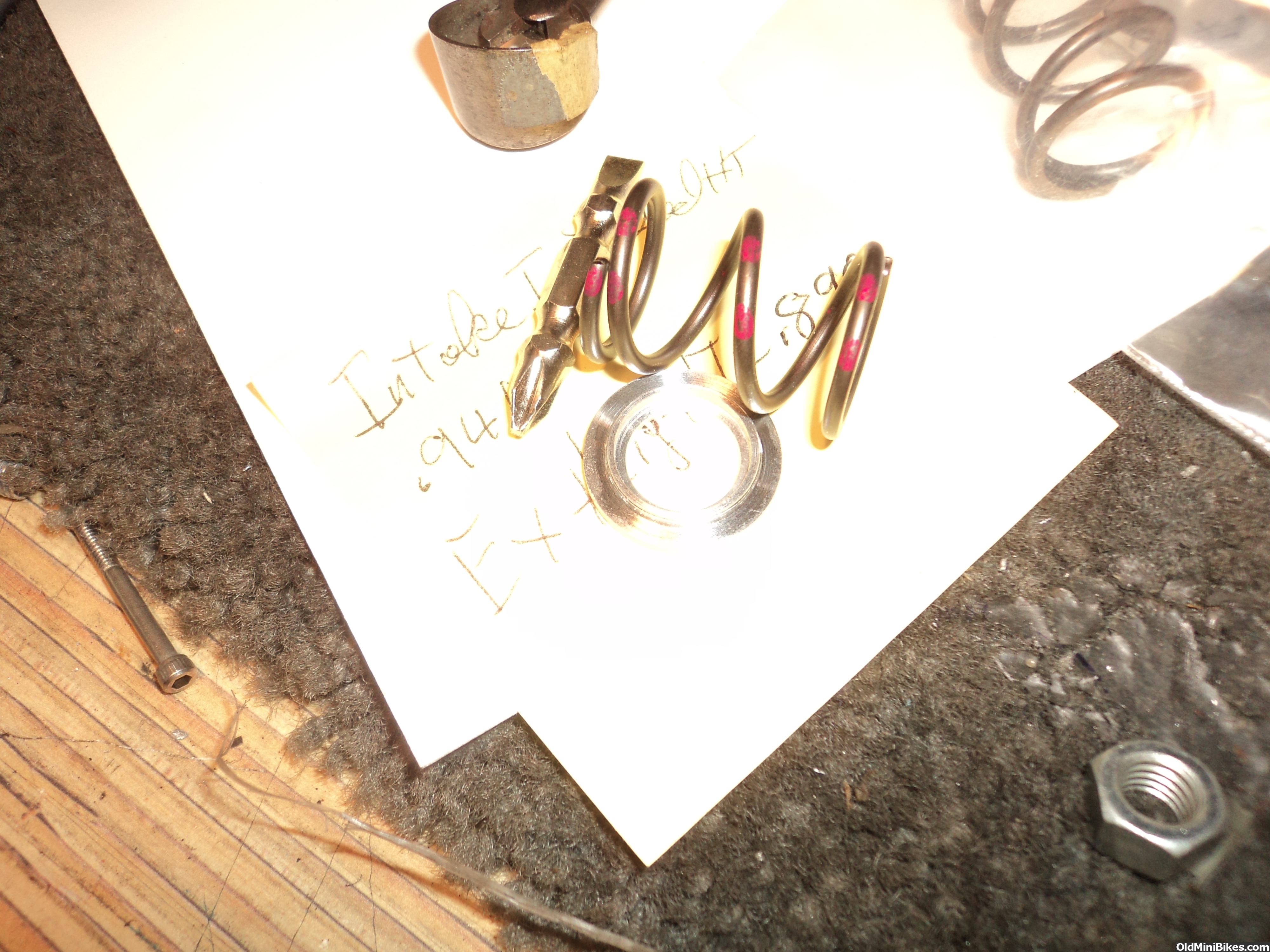
Did the initial porting but left stock 24mm exhaust seat and no seat on the intake yet. Wanted to see how it sounded and what it flowed so I could fix and initial issues and then see what difference the valve angles have. Intake sounded fine but I did not do any velocity testing yet, flow was down about 15% of what I usually see with a finished port. Exhaust sounded nasty a low lifts and using a flowball I found it went quiet with it up around one side of the valve guide. I have to see if I screwed something up there but flow was also a bit low but I still have to open the throat .040 and cut the seat for a 25mm valve. I did flow it backward as it is a pain to reverse flow of the bench and recalibrate so until I am finished I do them backwards


Last edited:
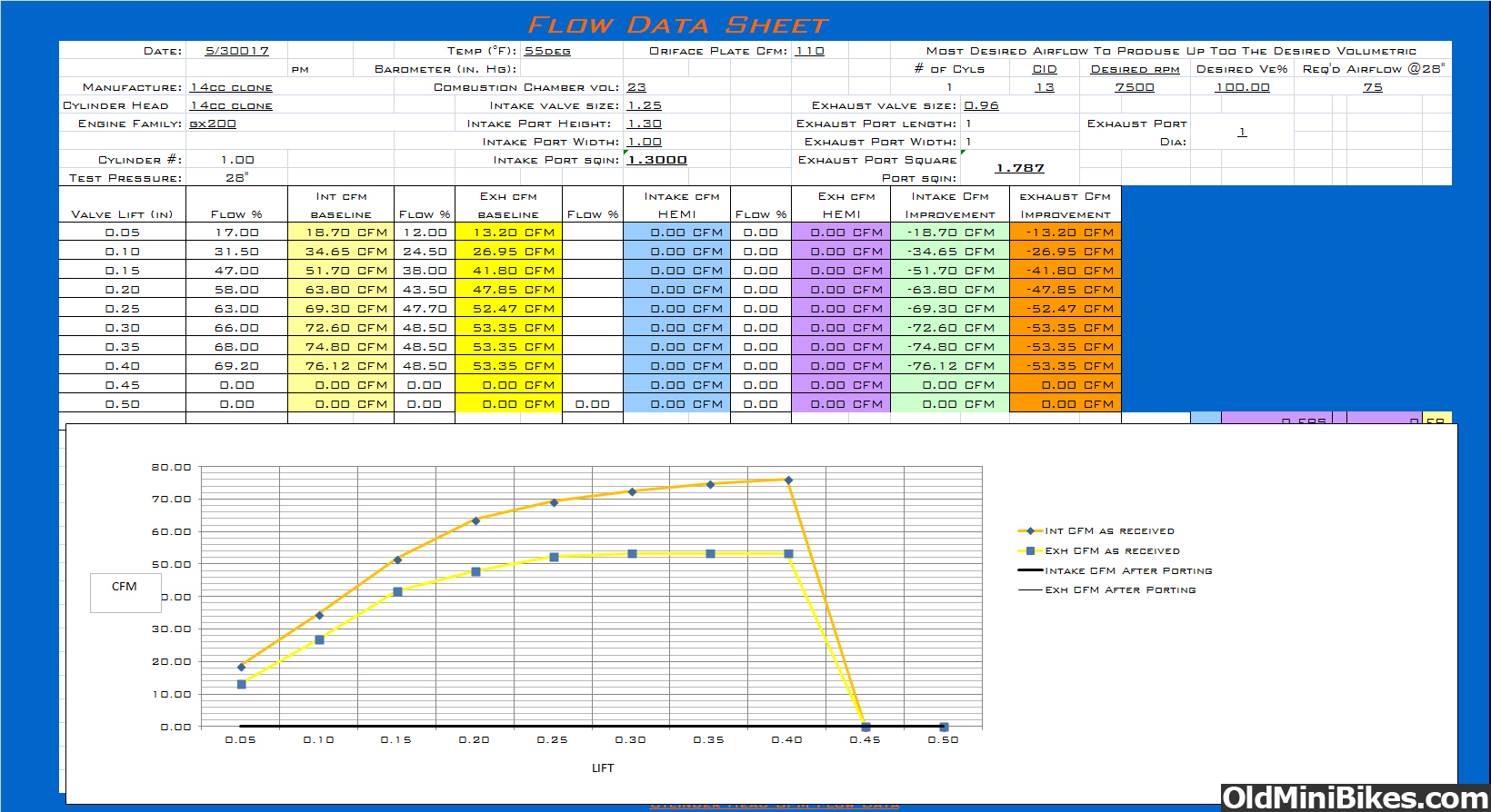
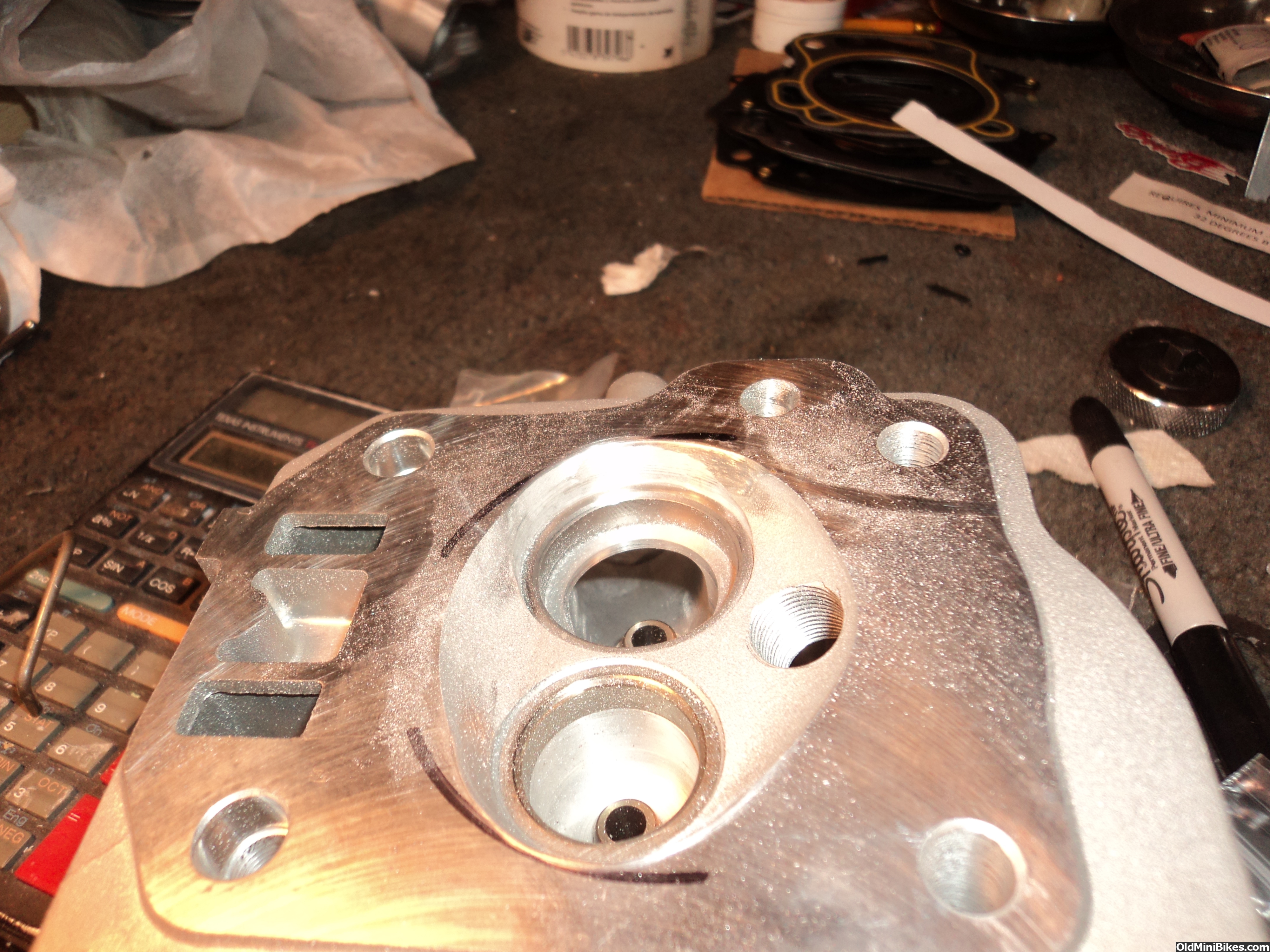
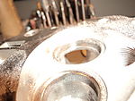
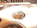
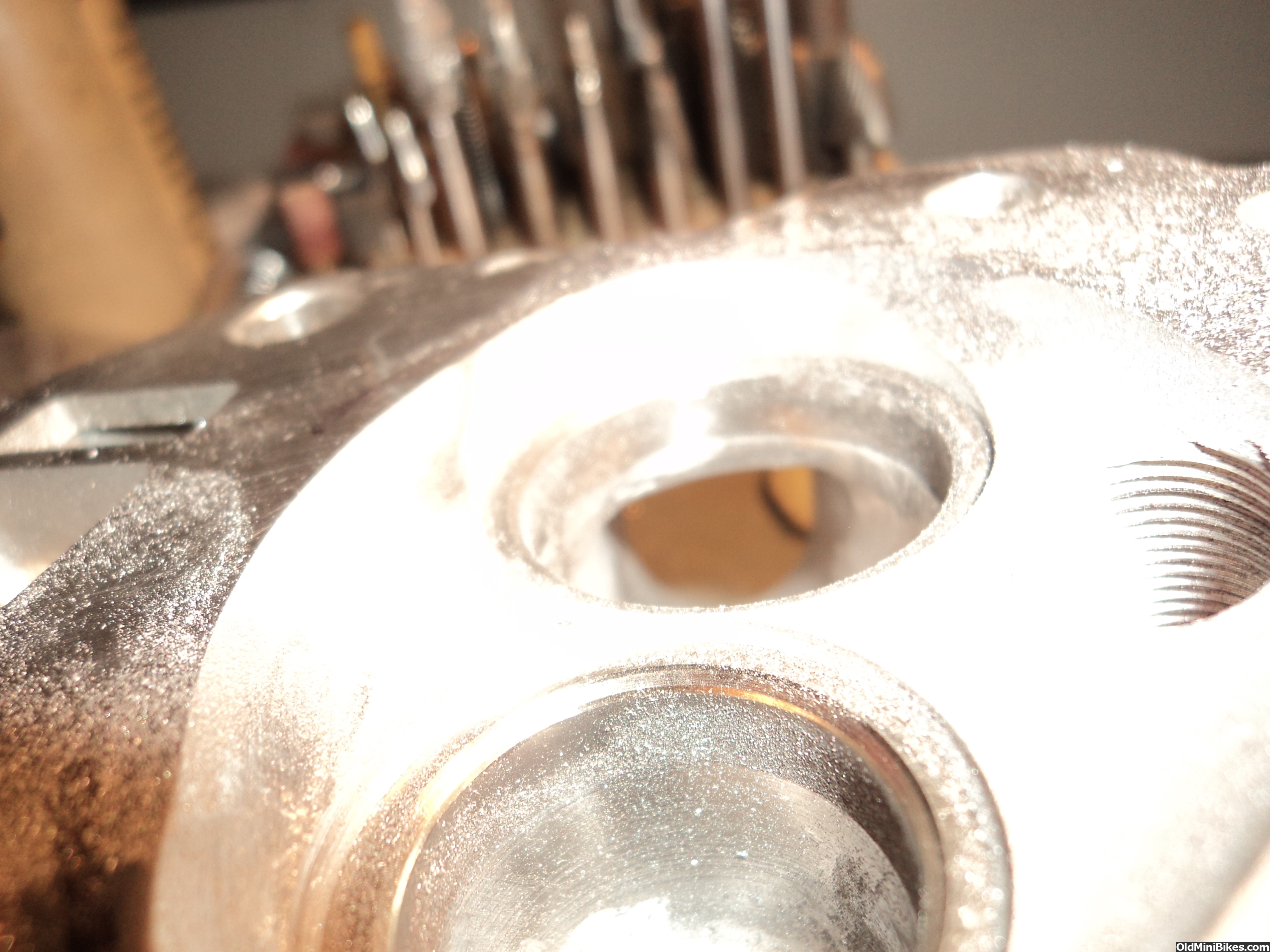
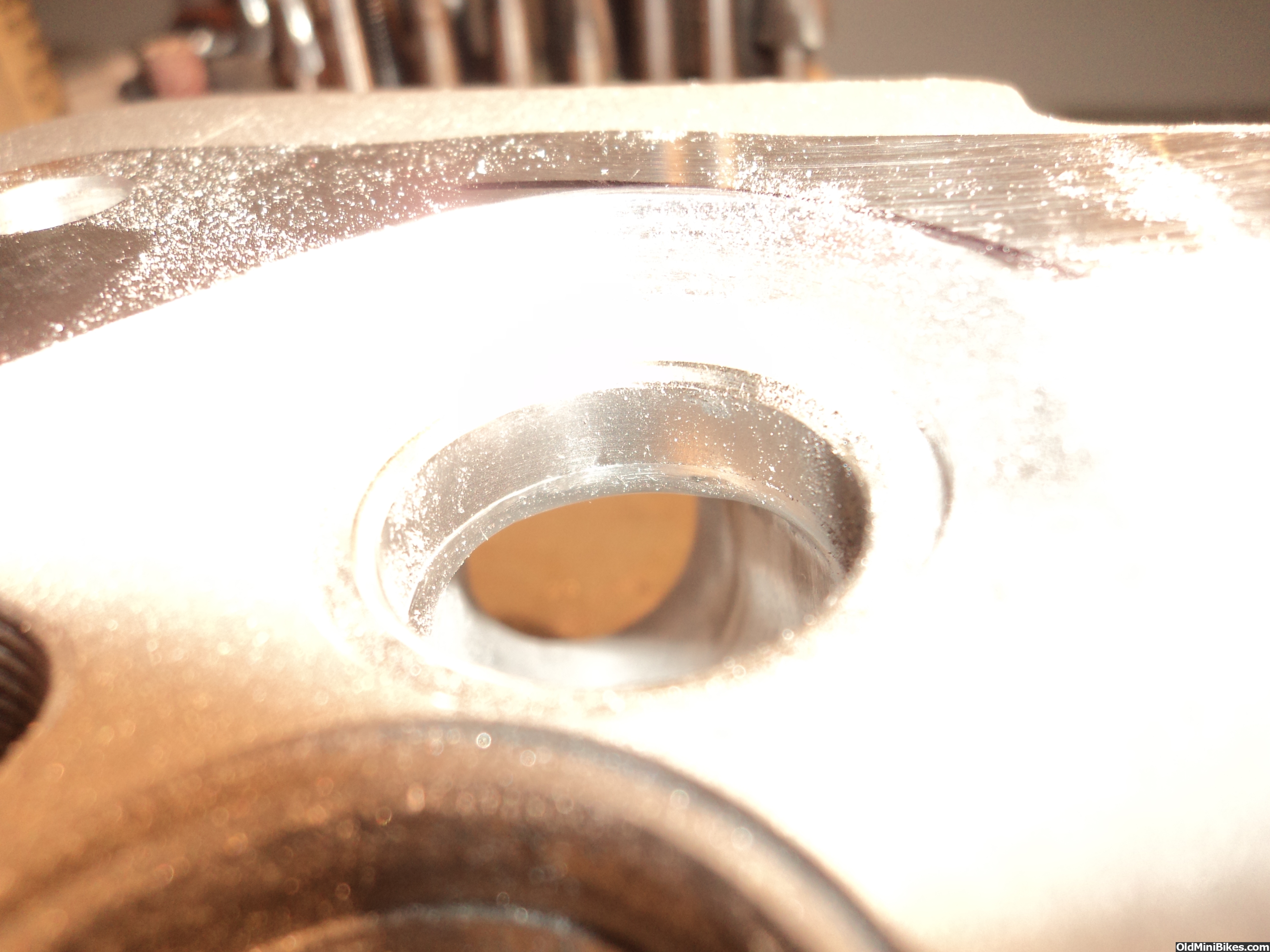
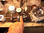
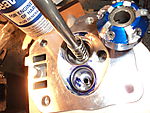
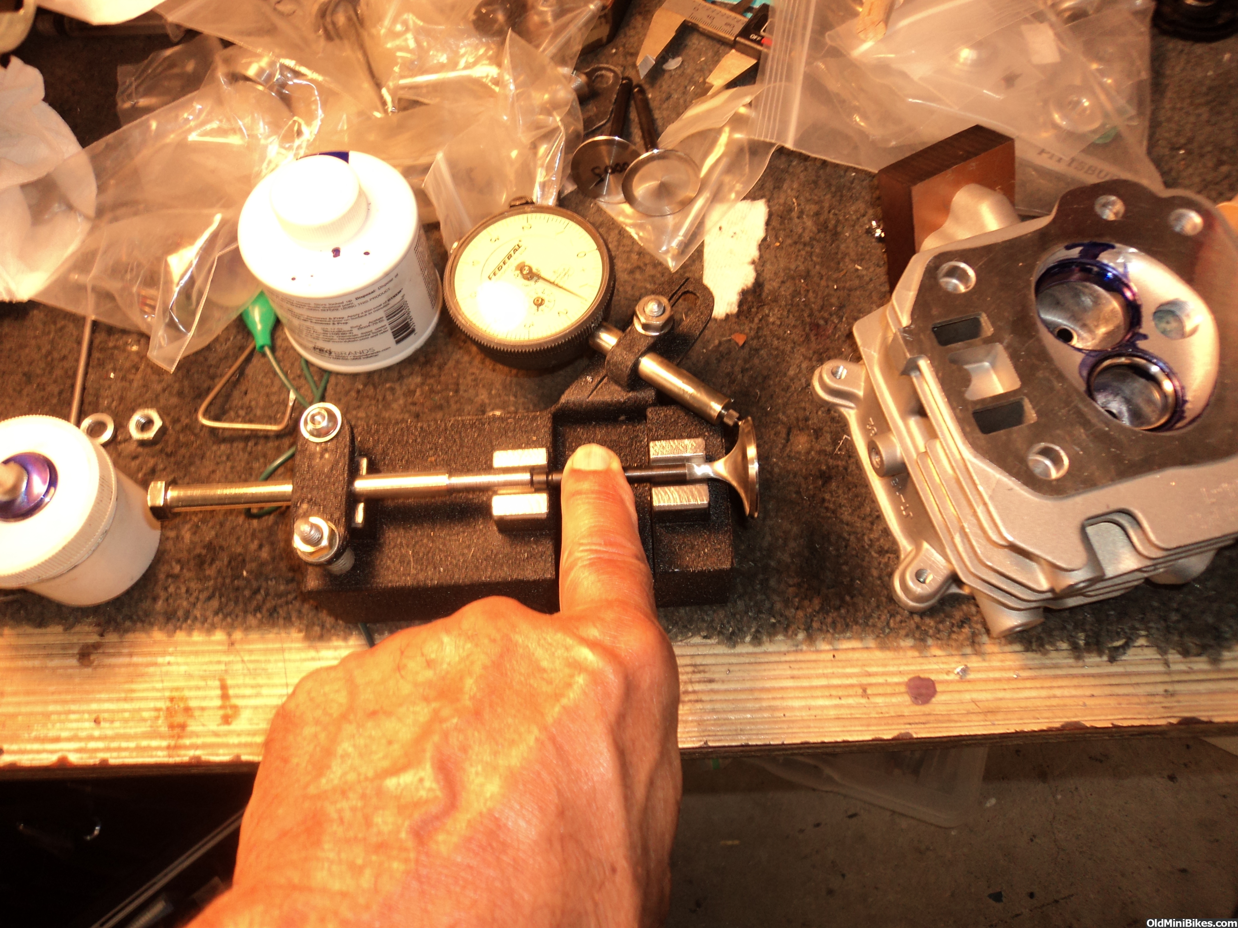
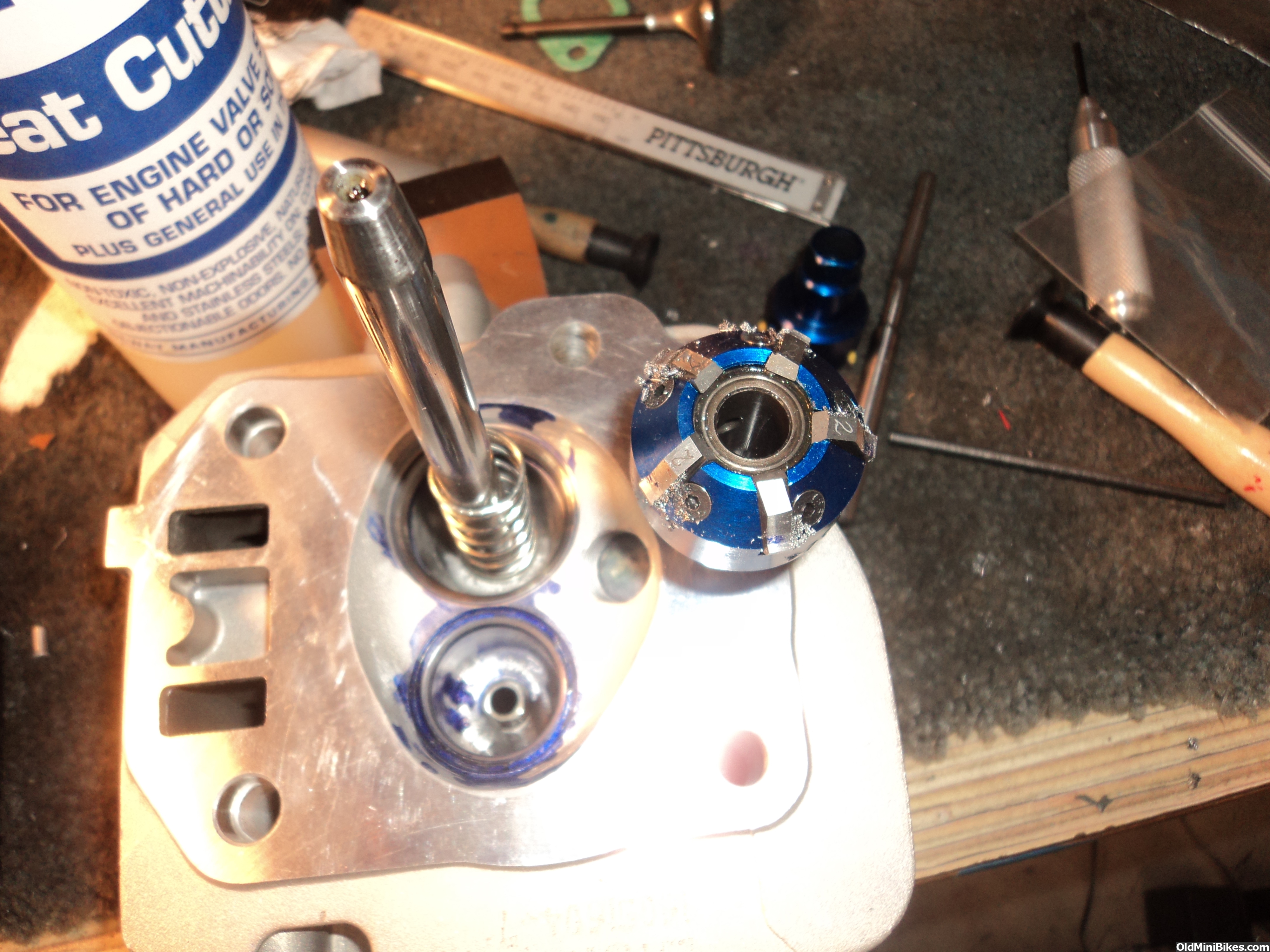
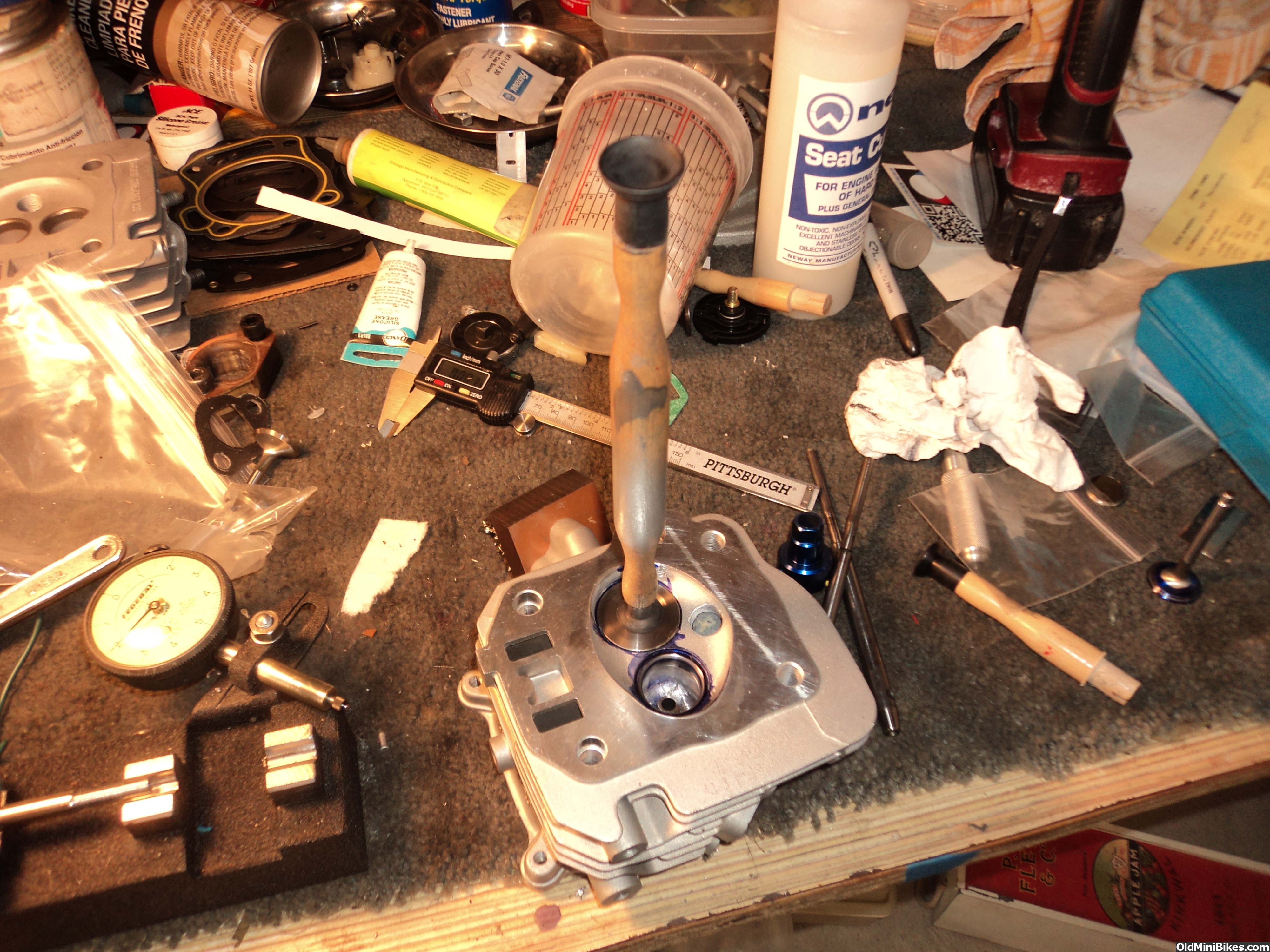
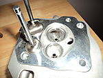
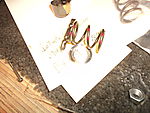
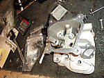
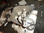
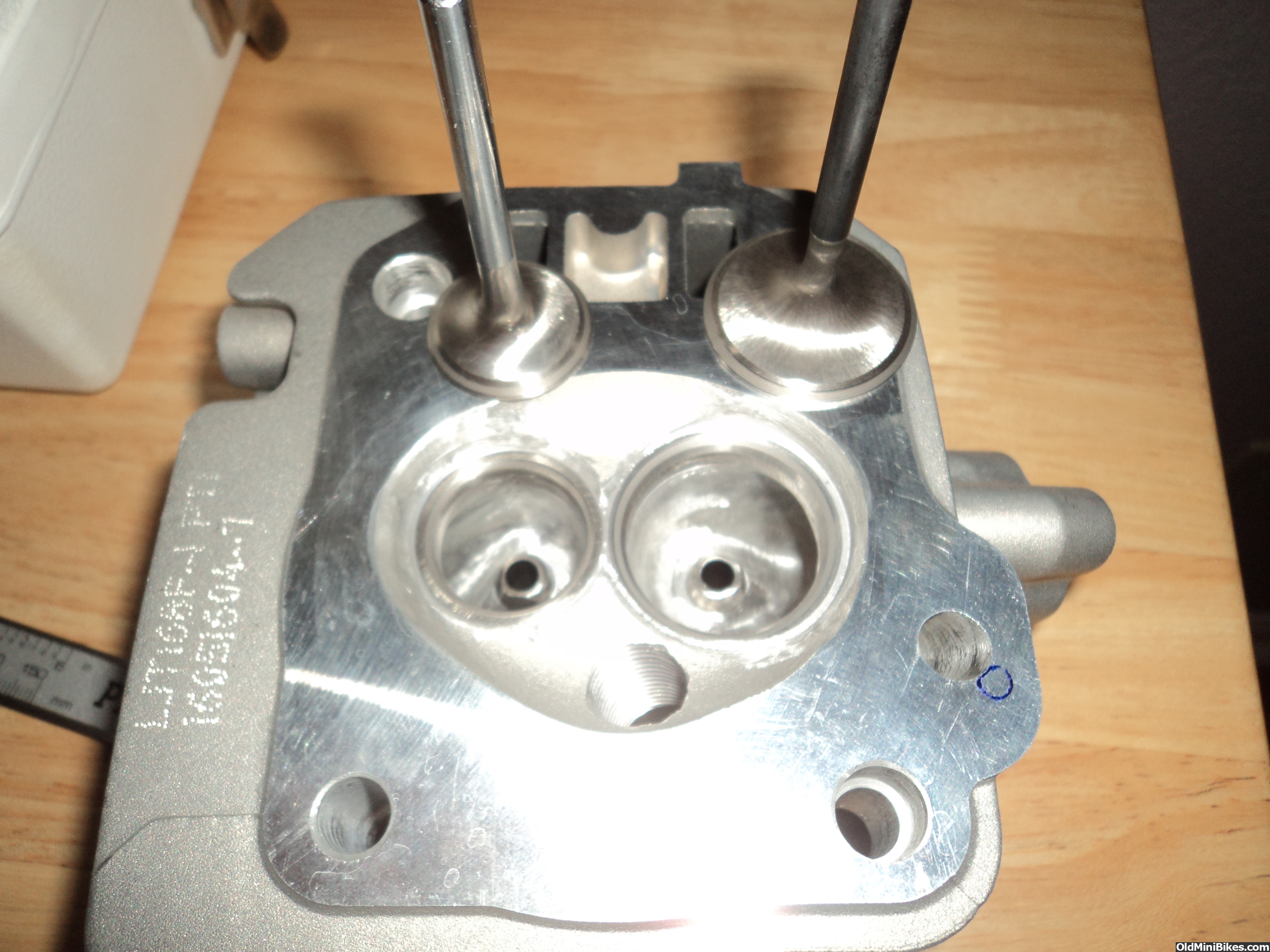
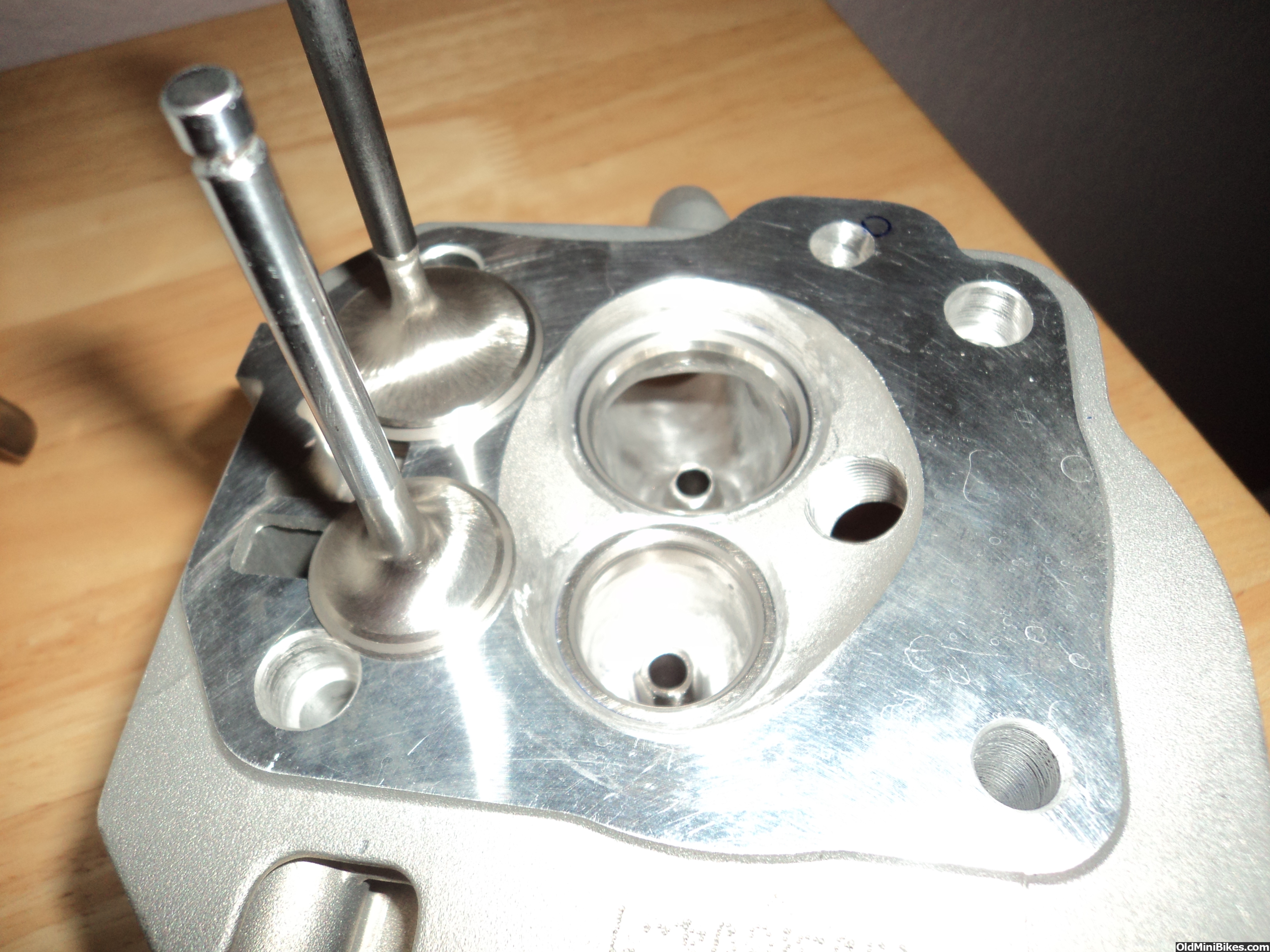
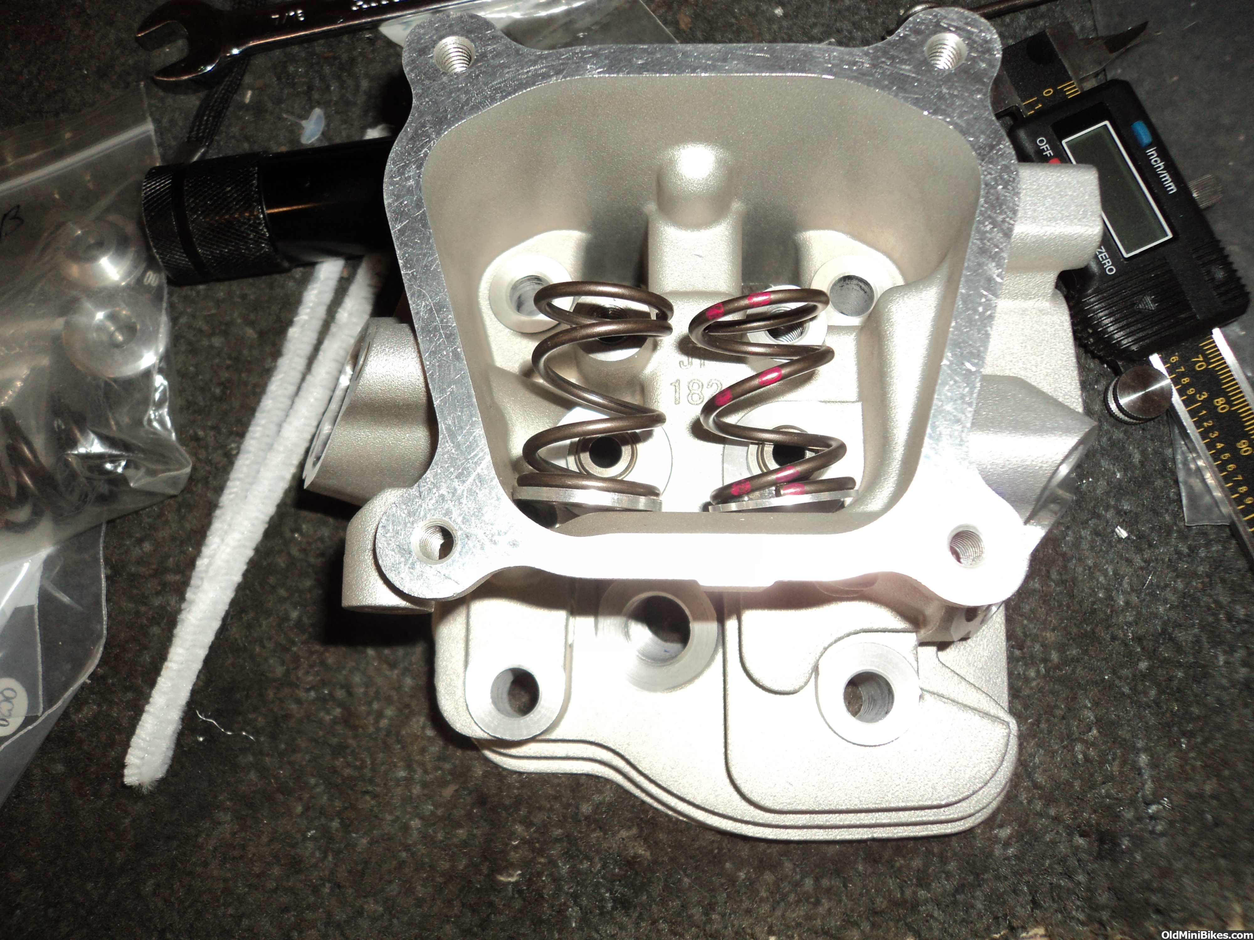
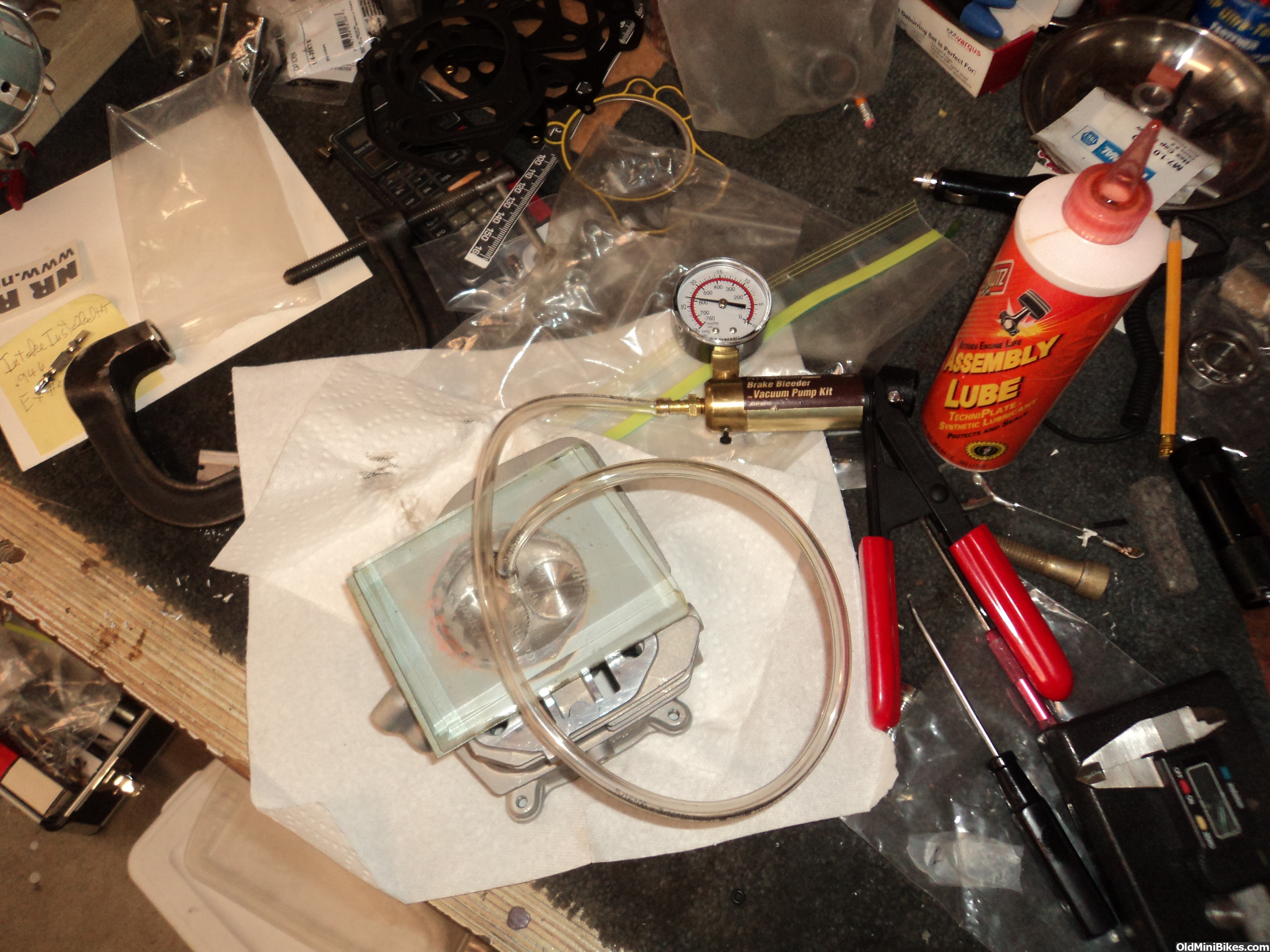
Well after some more short side work and tweaking I did get the flow up but the exhaust port does not sound good when passing air. Will do some velocity probing to see if any areas are bad. Tried the flow balls and did find a exhaust issue and laying back the short side seemed to help although it is counter intuitive. Here are some pics of the valve job and lapping process. Also checking valve face runout. Stock valves always check fine but the aftermarket valves are all over the place as far as face runout.

")
It is the way the face was ground. I think all the ss valves come from the same supplier. I am sure they have a number of grinders and maybe one is suspect. If the stem was not straight It would cause the same issue however on the ones that have .003 or greater I can see the margin vary which tells me it was not ground correctly. I will go put an indicator in the middle of the stem just to check as you bring up a good point about the stems.
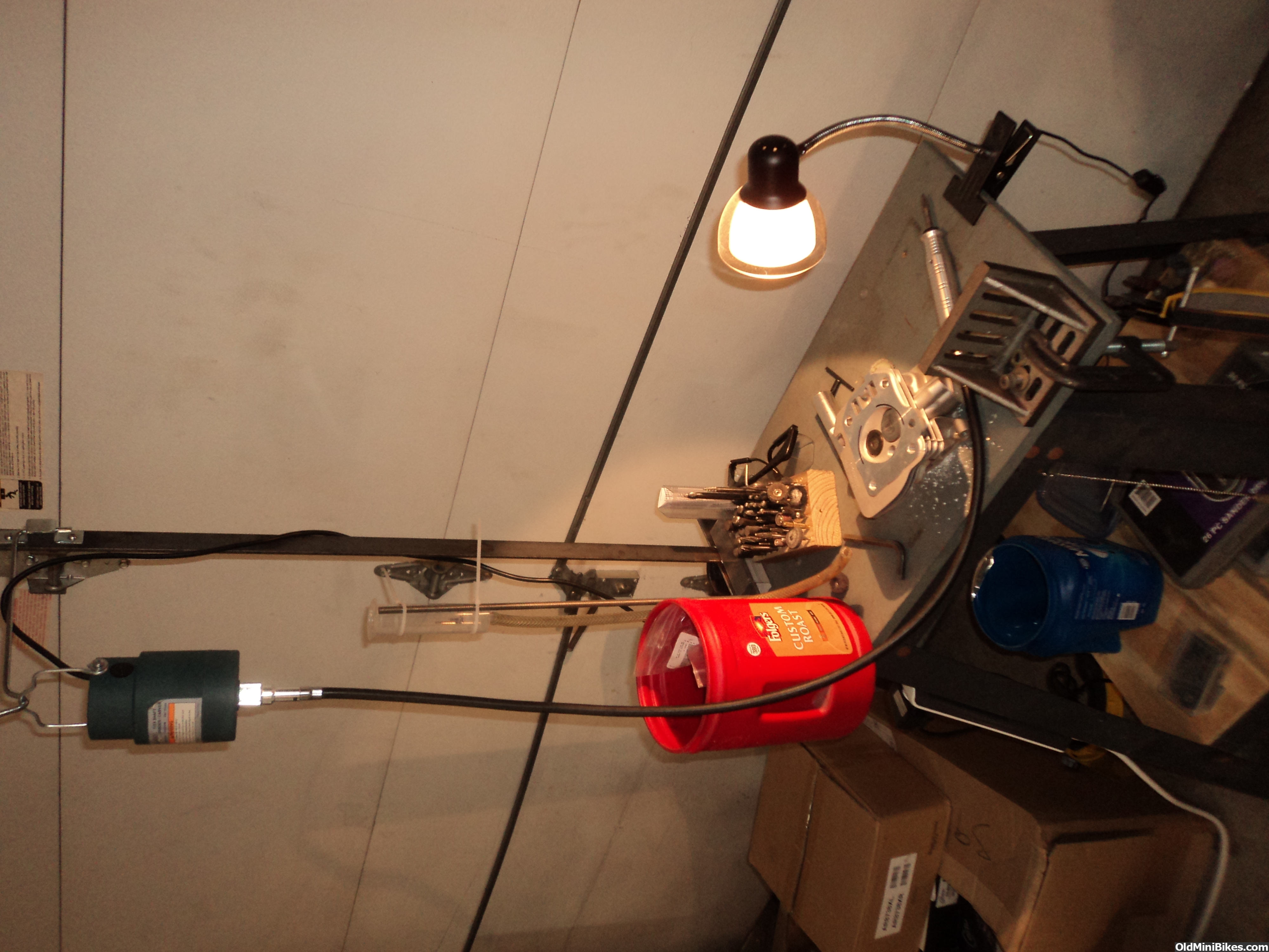
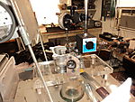
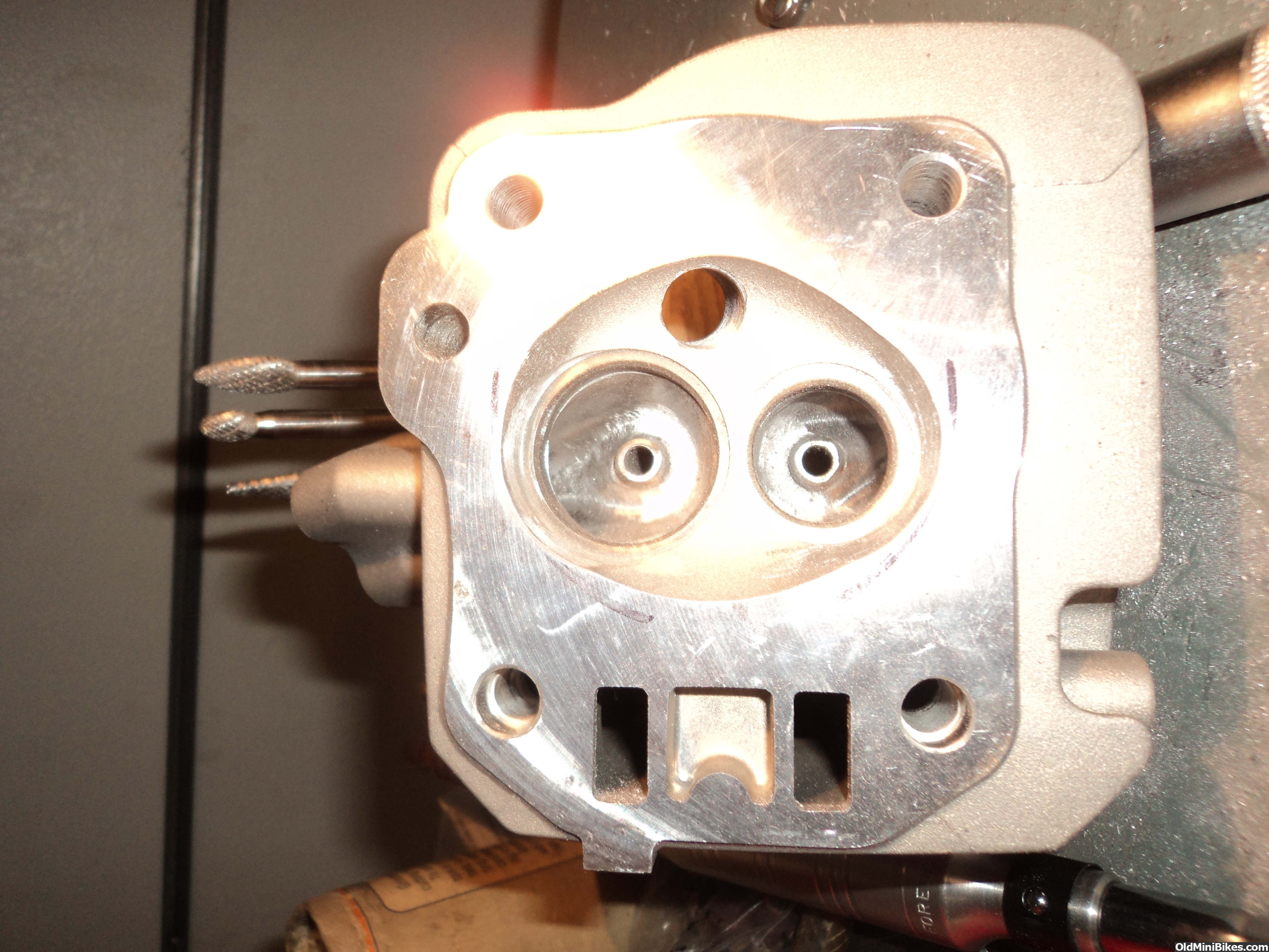
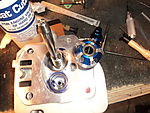
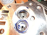
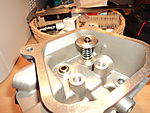
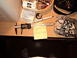
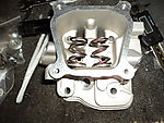
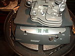
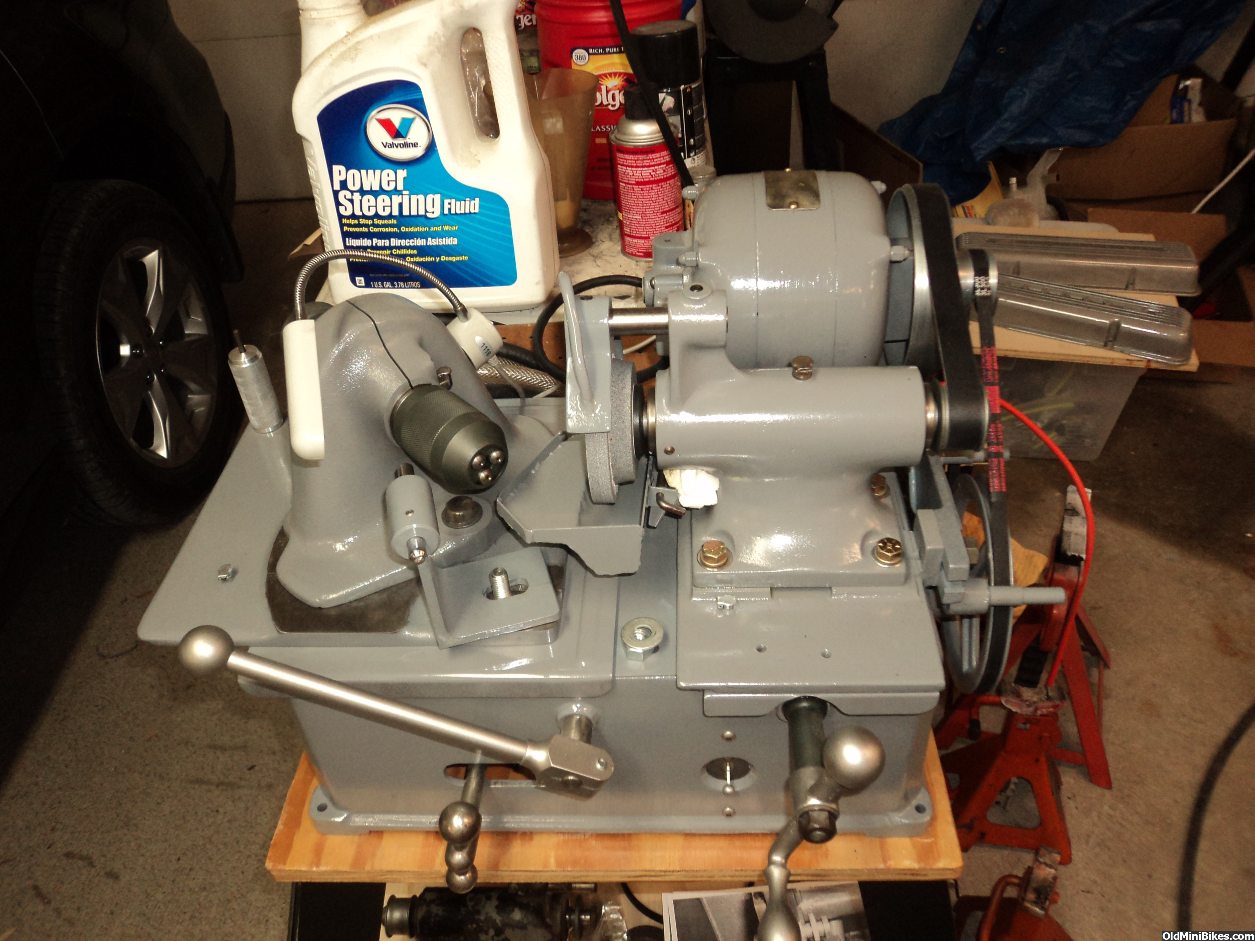
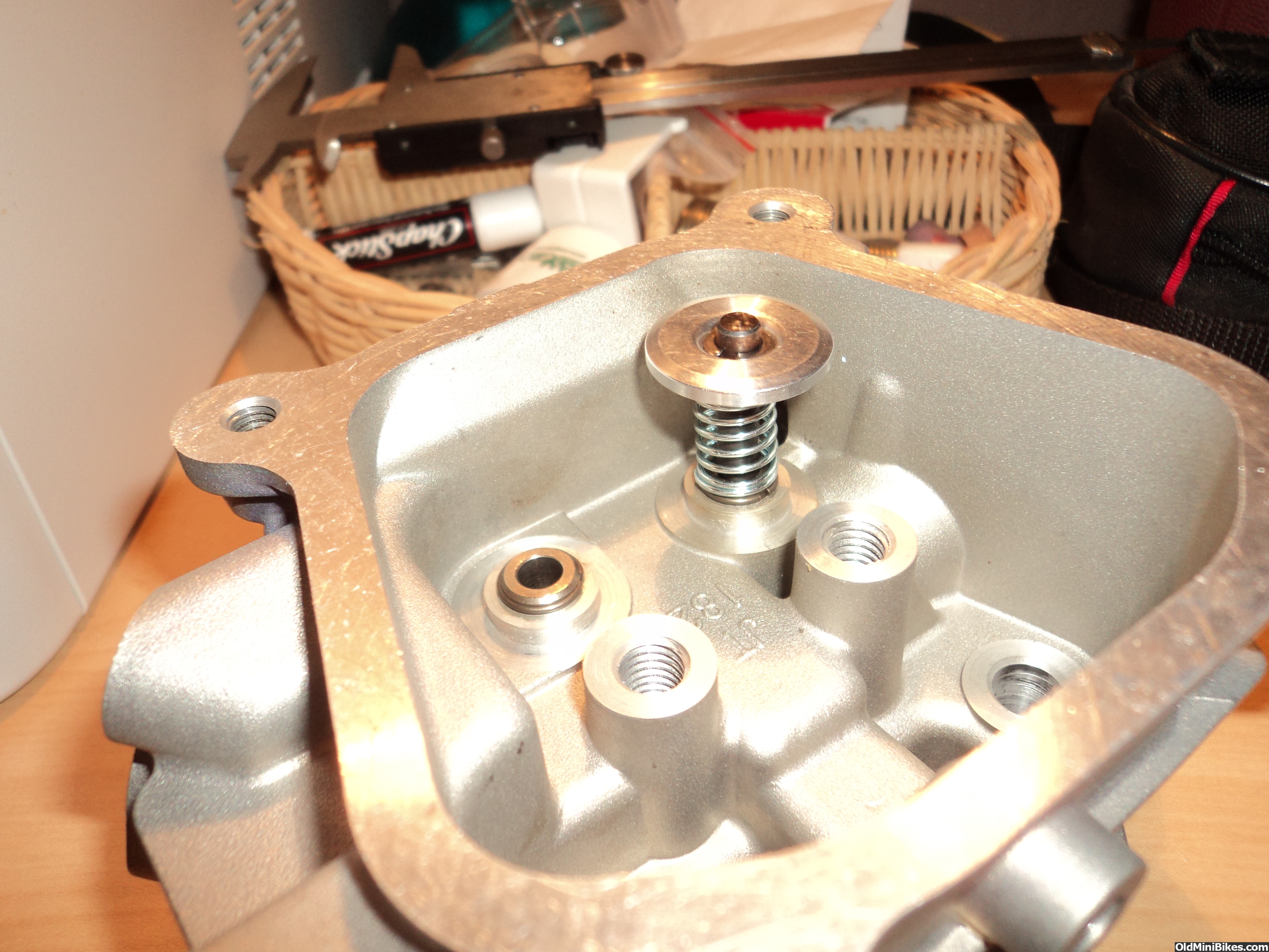
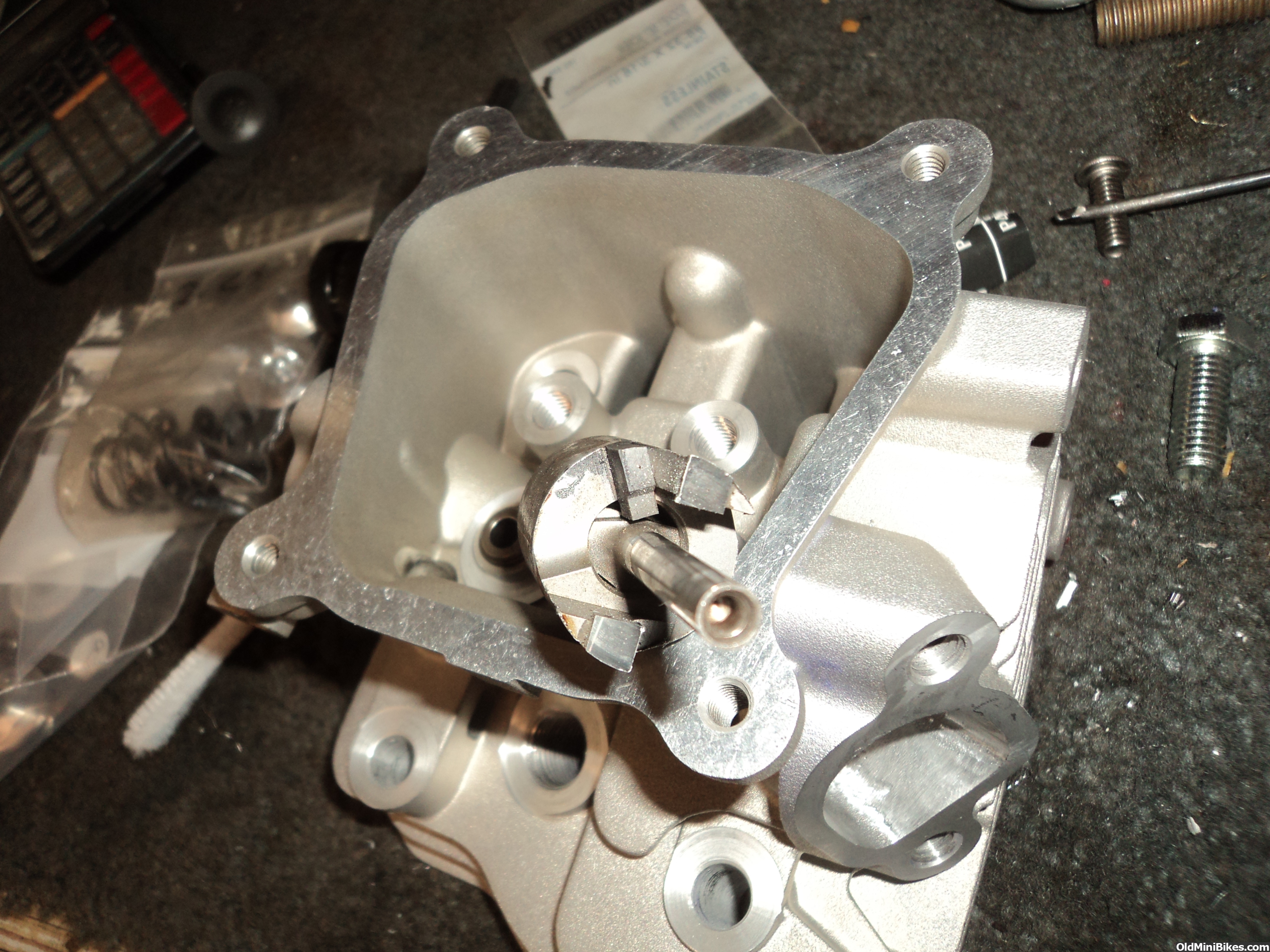
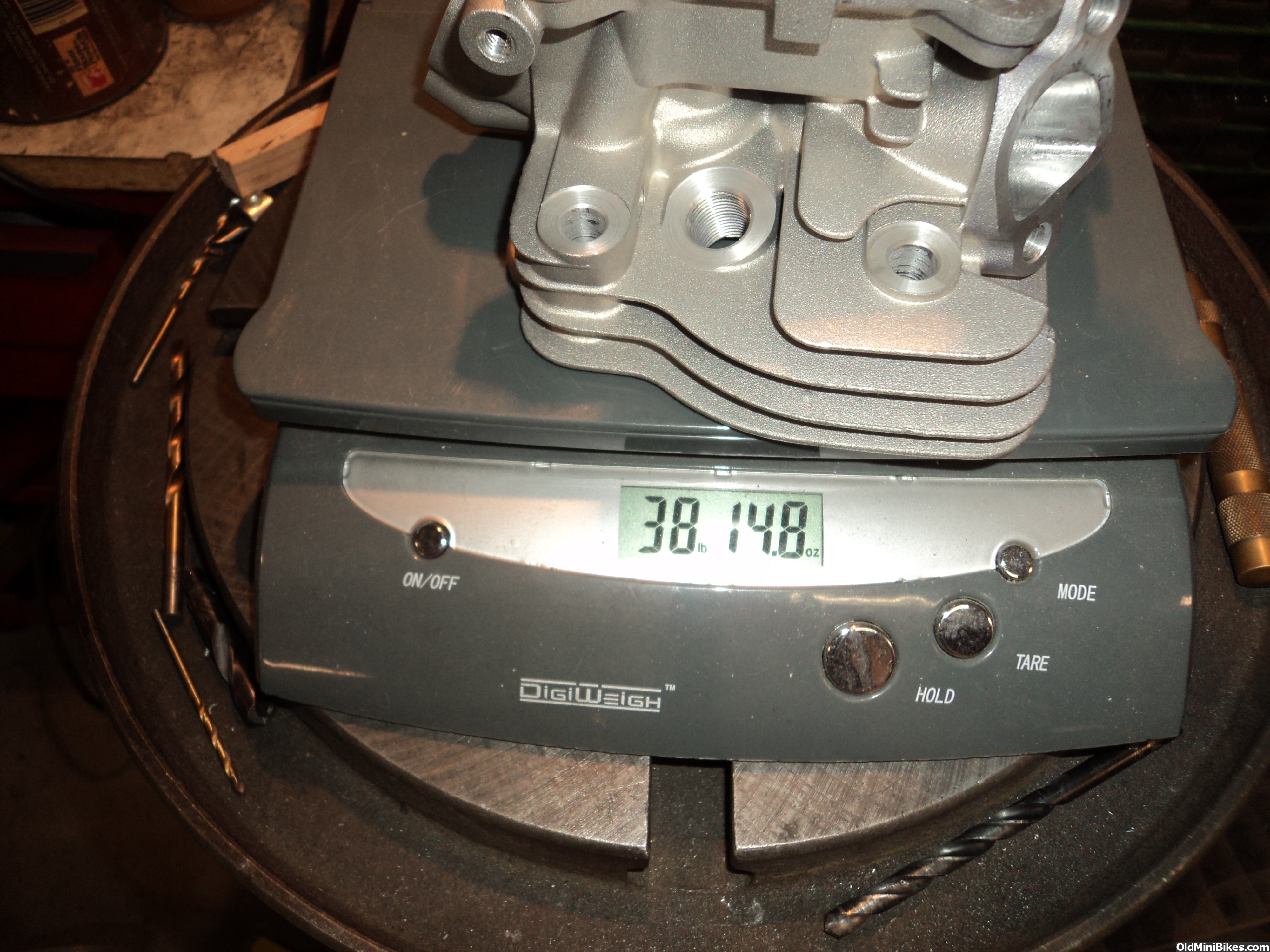
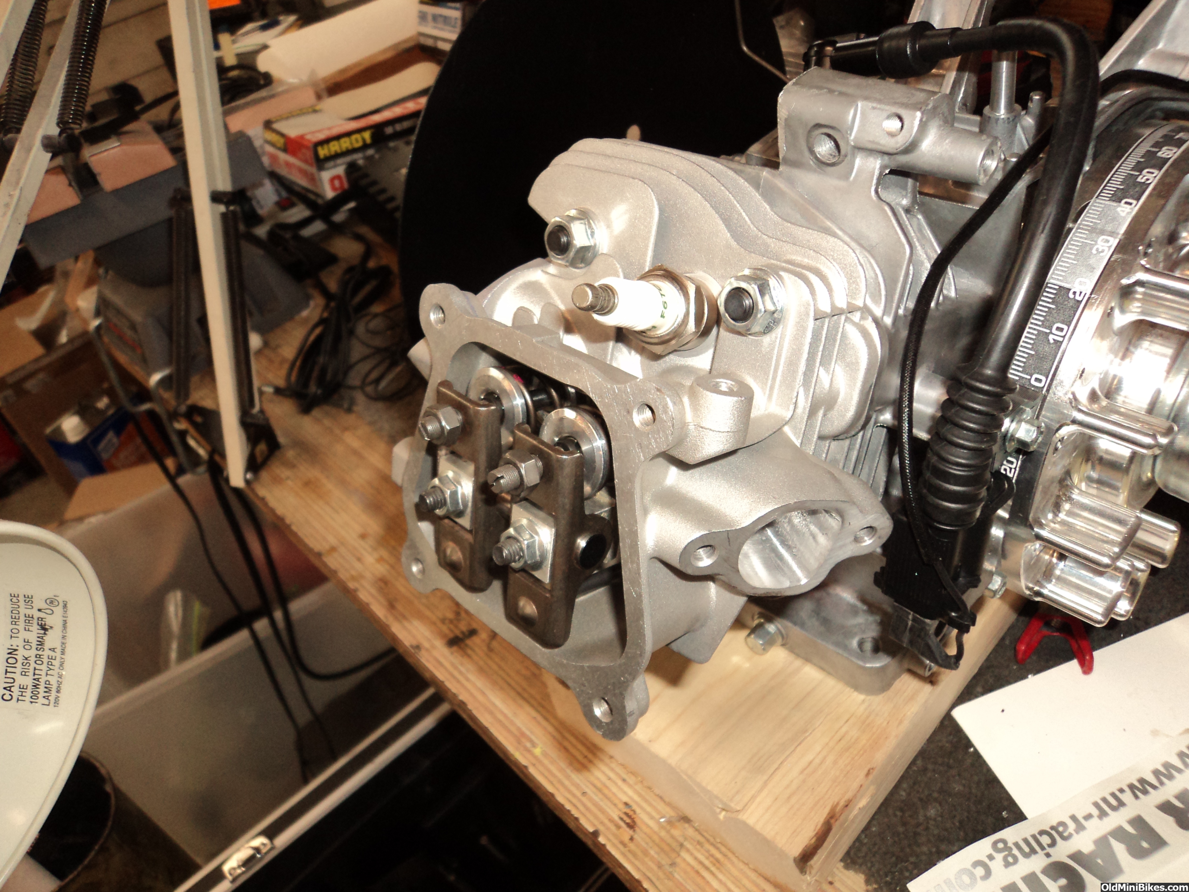
Well its been a while but I was sidetracked by purchasing an old Sioux valve grinder and the rebuilding of it and fabrication or some missing parts. So for the 14cc big valve head I was working on I was able to grind the exhaust valve and reduce the runout, and also put a 30 degree backcut on the intake valve and the machine works great. I had to grind them dry as it was a dry grinding machine but I have made up a drain tray and added a oil feed to the wheel guard so now I need a pump and reservoir. I finished the porting, valve job and vacuum test, then cut the seat pockets and guide boss and made some custom shims to fit tight to the guide boss and hold the bottom of the spring. Both valves had installed heights greater than .850 which is why I had to make up the shims. I checked the seat pressure and it was 38 and 40 lbs of seat pressure. These are 37 lb single springs. Next up is to calculate the correct pushrod length which is off with these 1.3 stout racing rockers.


ole4,
can you tell us rookies how you are determining proper pushrod length? With the V8 engines, we set the lash and rotated the engine and with some die on the valve tip we were making sure the rocker (or roller in your case) contacts the center of the valve stem. We had adjustable pushrods to check this. How are you doing this?
can you tell us rookies how you are determining proper pushrod length? With the V8 engines, we set the lash and rotated the engine and with some die on the valve tip we were making sure the rocker (or roller in your case) contacts the center of the valve stem. We had adjustable pushrods to check this. How are you doing this?
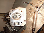
I will be happy to show you the process. What you said above Is how I check It when I am done but it can be a bit more complicated. You ideally would want to have the minimum sweep across the valve and get no closer that around .030 to the inside or outside edge of the valve. With the valve closed the tip of the rocker should be inboard ( closer to the rocker arm piviot) then sweep out up to the midpoint then back again. When mixing up parts like I am doing with different rockers and valve lengths it is not always possible to get it centered. It is not so critical with out motors as the springs are not that strong. I car race engines when the sweep is off toward one end the guides get a lot of side thrust and wear. In my case I have two different length valves and shaft mounted rockers so geometry needs to be individually adjusted and may not be ideal in the case of the longer than stock intake valve. I have to make up pushrods for this and I'll take some pics on how I calculated the length.