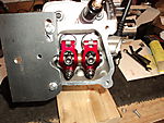
Those are not roller tip rockers E ...Very similar to the new champion style though .. but you bring up a very good point you can see his geometry is set perfect !!!
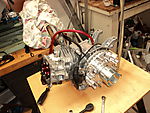
Building a non hemi predator Test Motor

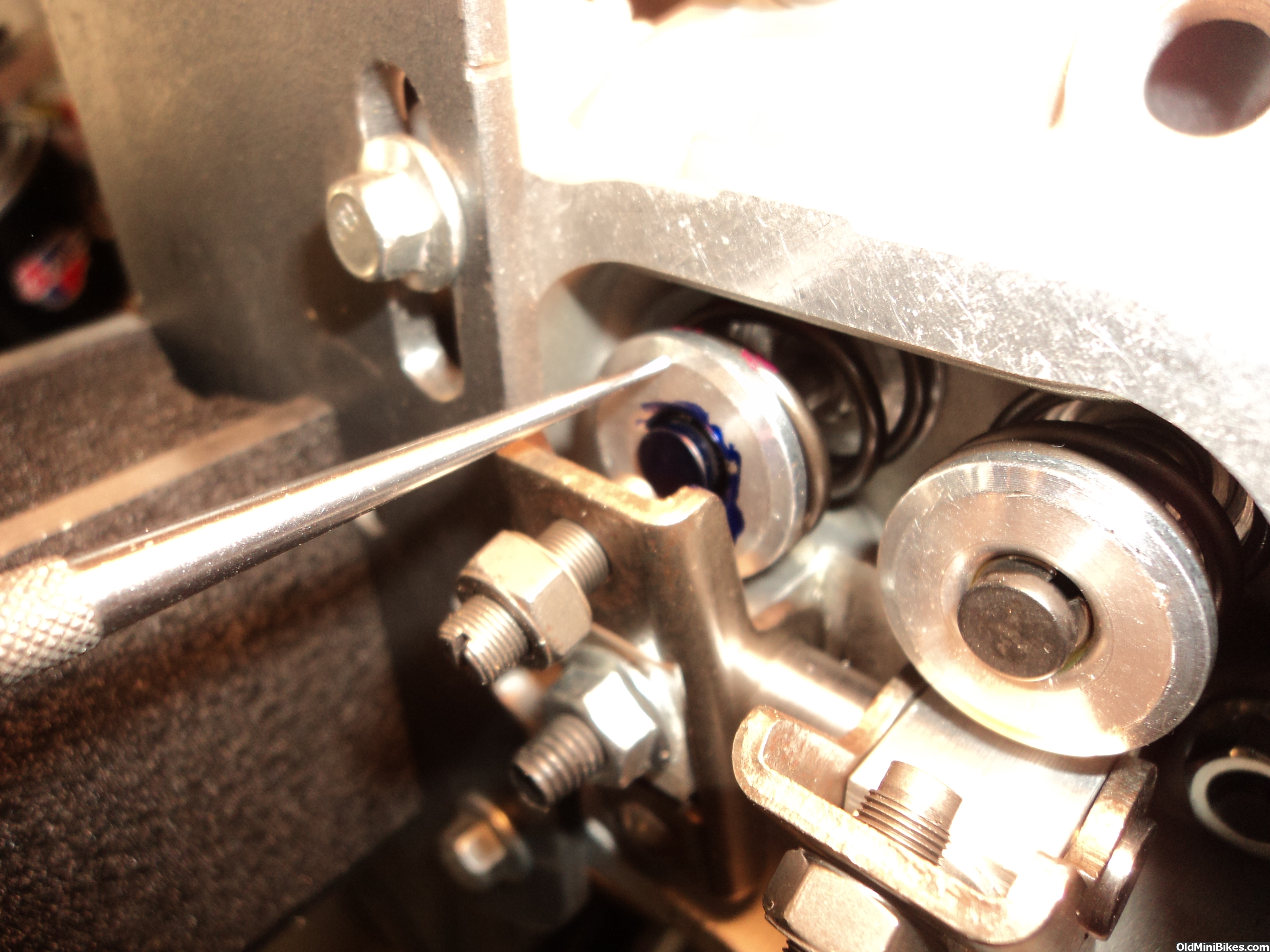
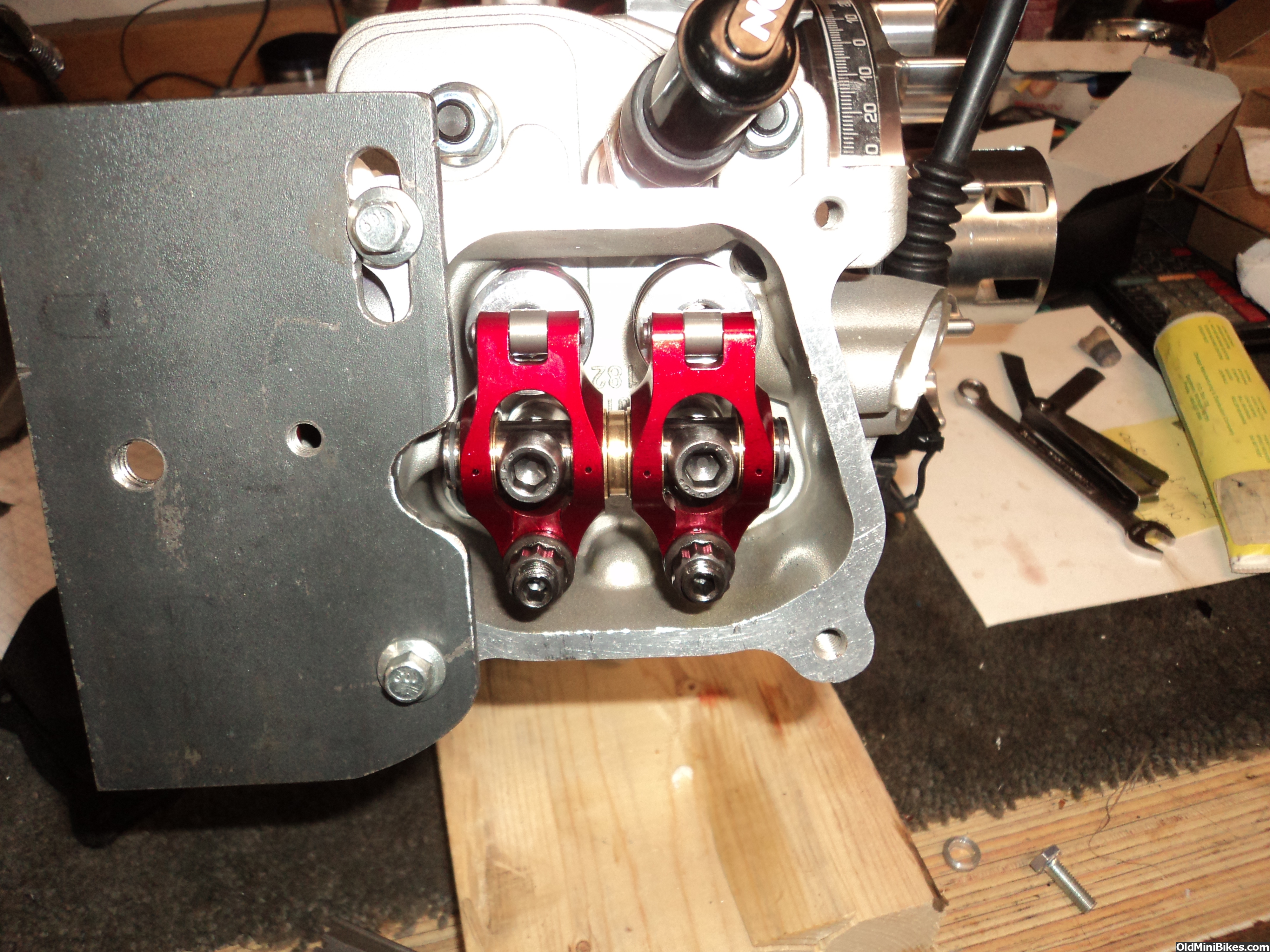
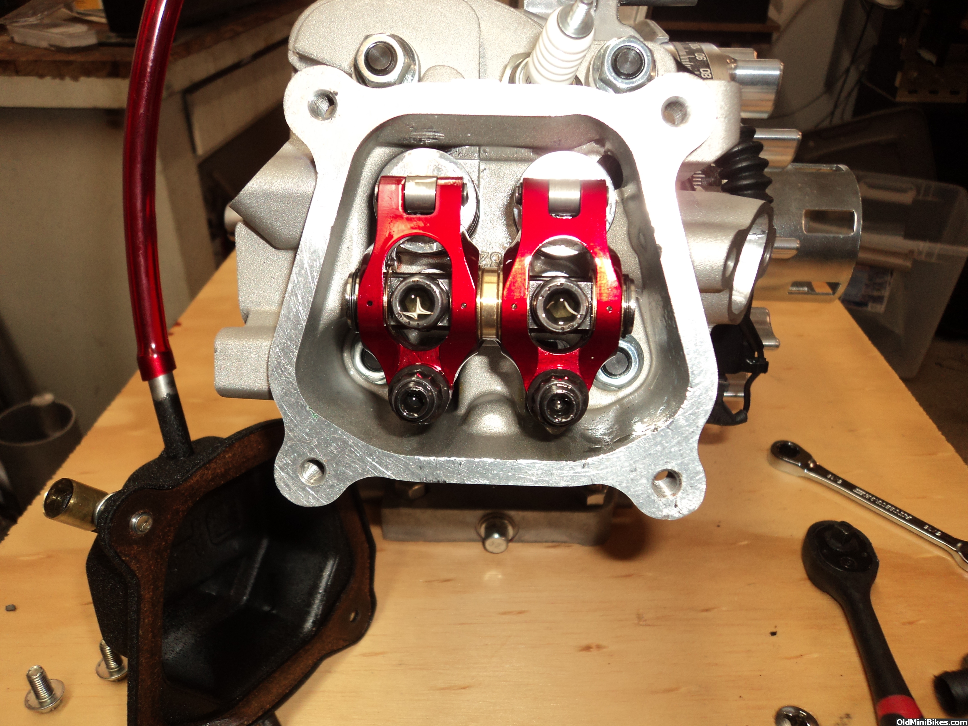
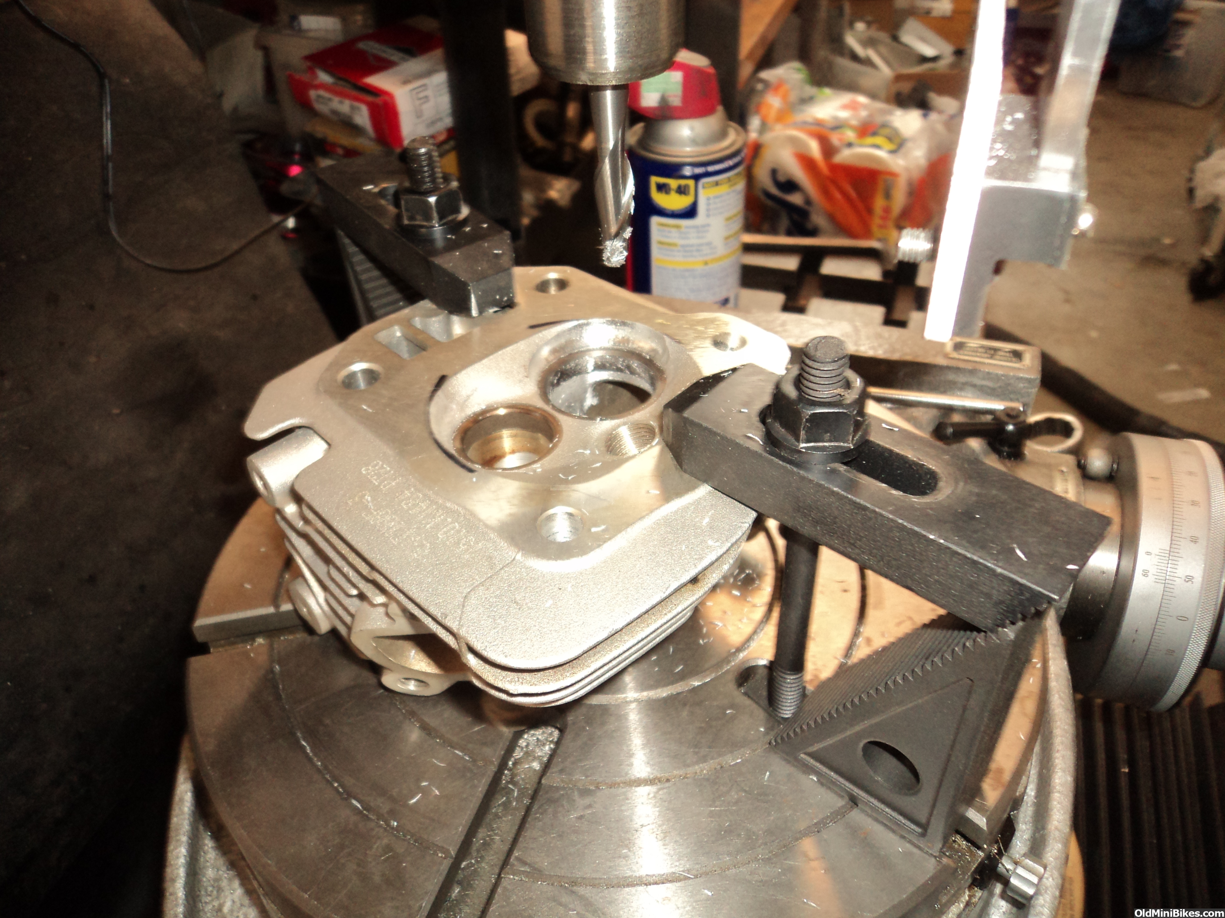
So I made my pushrods and had to make two different lengths to get geometry close. I use a adjustable pushrod made from a isky chrome moly build it yourself pushrod. I cut it and threaded both lengths for 6-32 thread and insert a 6/32 stainless stud inside so I can cover from short to long. then I looked at total lift divide by two and eyeball when the rocker is 90 degrees to the stem. I check that I am between 40 to 50 percent of total lift when rocker is perpendicular to the valve. There are a few adkustments to get geometry correct and they are rocker arm fulcrum height. pivot distance to the valve and pushrod length. In my case I only have pushrod length on this engine. Our stud locations are not movable so that one is out and on shaft mounted rockers where both are on the same shaft the height can only be adjusted with shims on both. I just bolted mine in and got the best I could get with two different pushrod lengths. As you can see from the photos the sweep is centered but kind of long. that is the best I could get. I tried longer and shorter but result was about the same. Also these are the rockers from Stout that are supposed to be 1.3 ratio but unfortunately that was not the case. Lift taken off the pushrod for the black mamba cam was .275 exactly to spec. Lift at the retainer was .295 so ratio was a little over 1:1.1
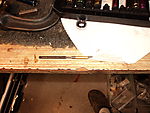
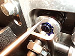
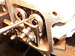
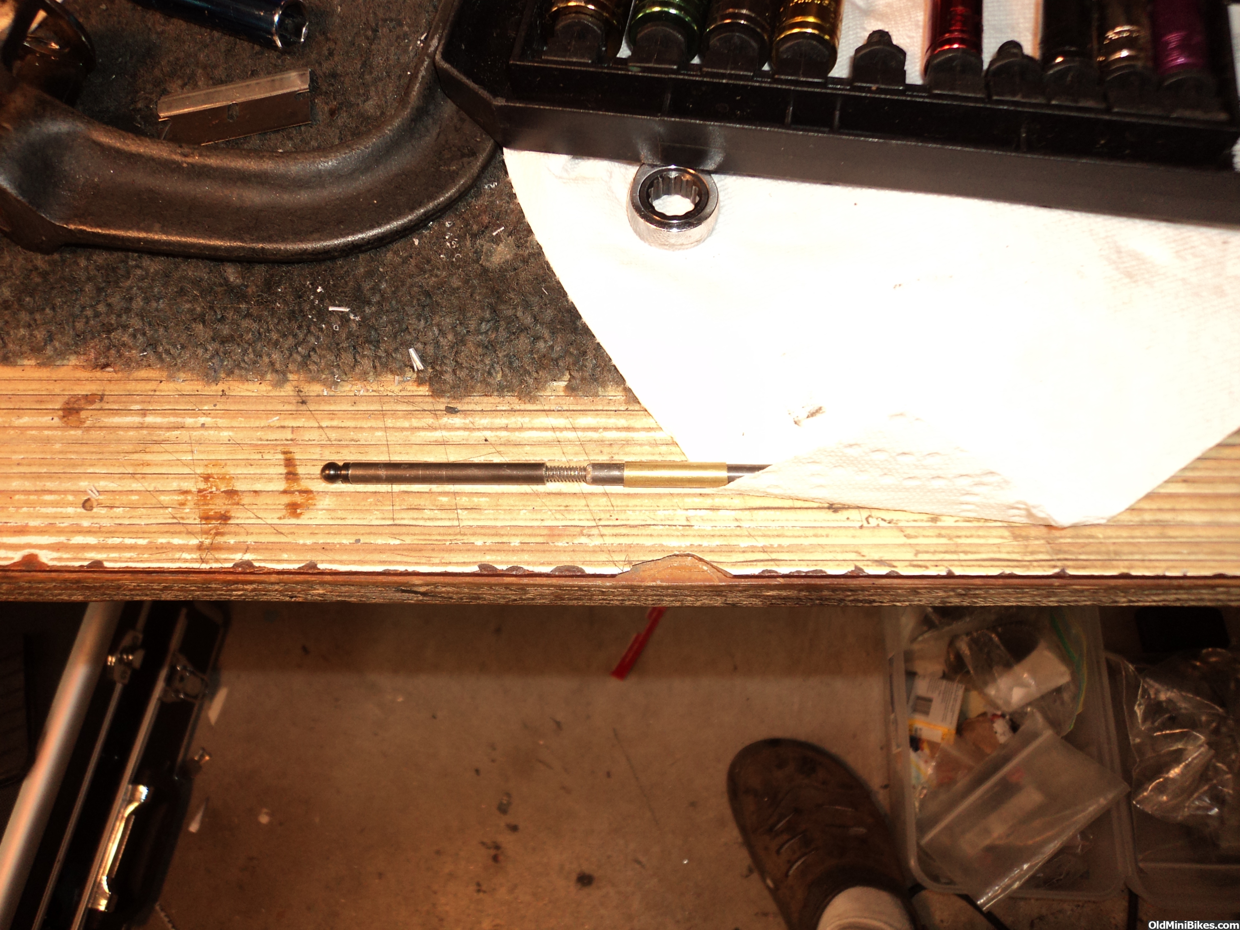
1) adjustable homemade pushrod. Brass sleeve is to keep threaded rod area stiff It slides over the threaded portion.
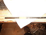
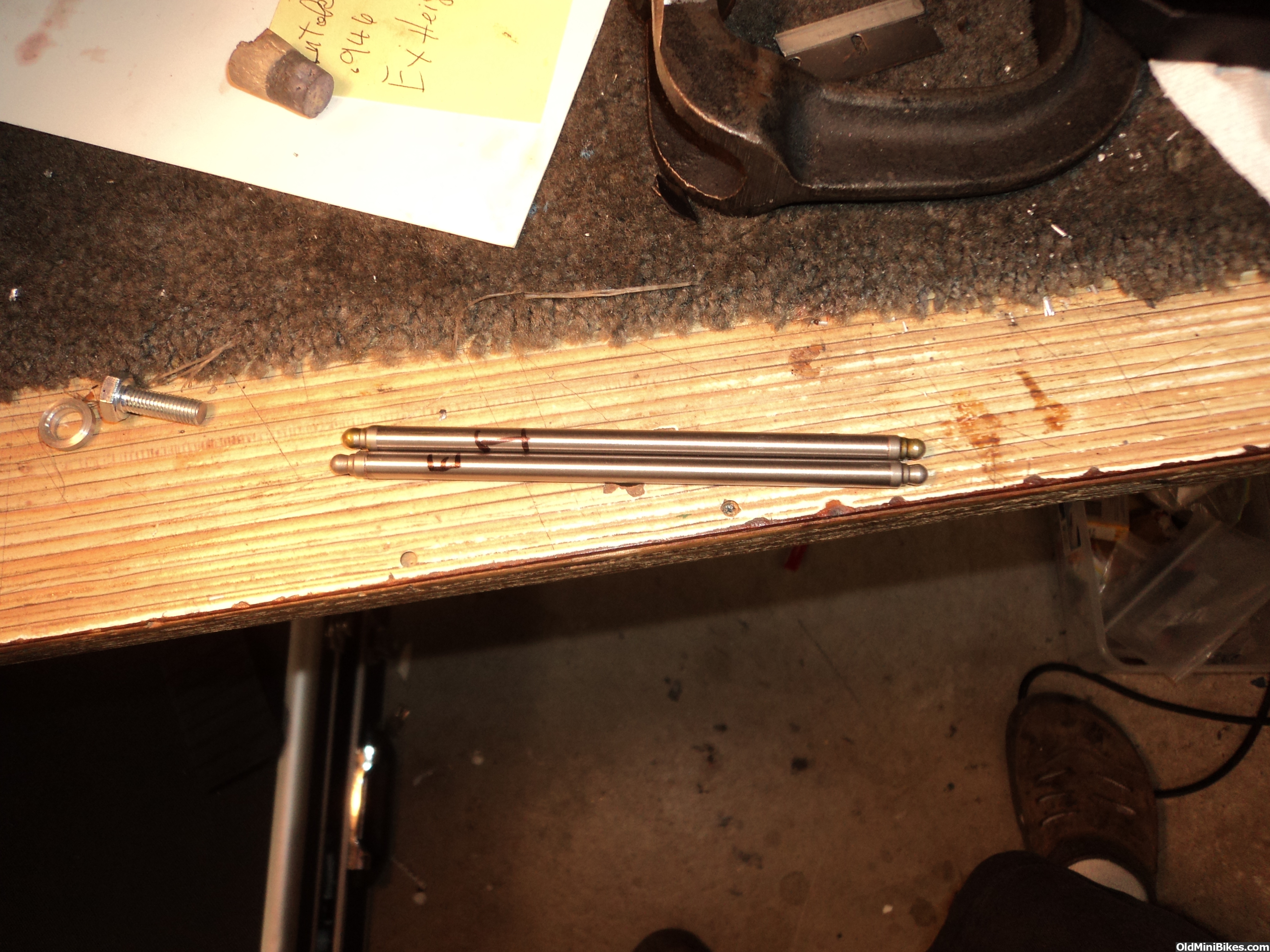
2) final pushrods
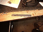
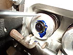
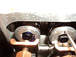
3) checking sweep, cam and valve lift.
1) adjustable homemade pushrod. Brass sleeve is to keep threaded rod area stiff It slides over the threaded portion.

2) final pushrods
3) checking sweep, cam and valve lift.
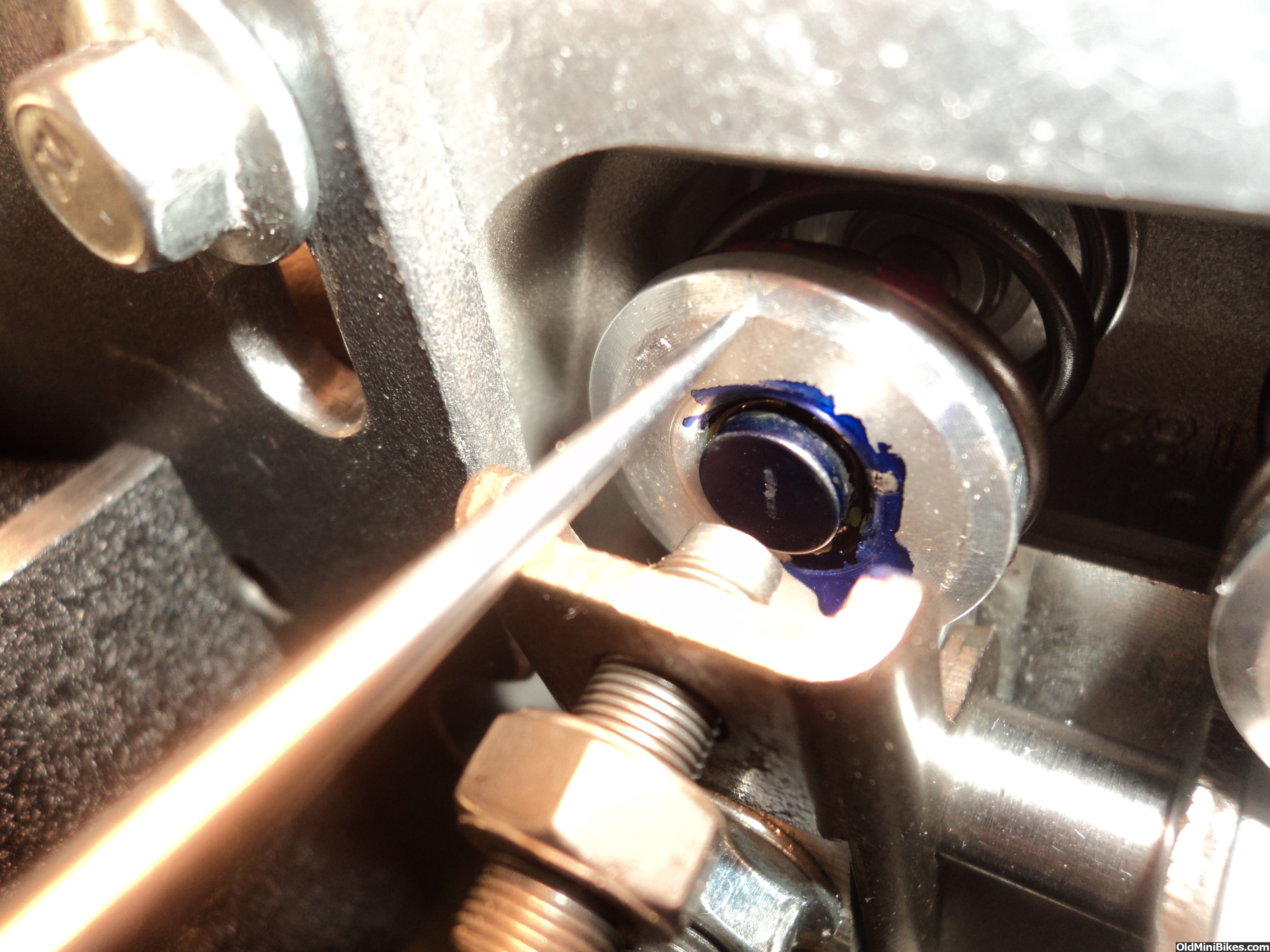


Well after trying to get geometry averaged between two different length valves I gave up. I have also decided to scrap the champion 1.3 rockers as I do not feel they are robust enough for the springs I am using. I took the head apart and ground down the end of the longer intake valve to the same length as the exhaust. Not there was not enough room for a lash cap so I used a high groove split lock to allow the use of a lash cap and removed the difference in spring height from the bottom shim. Now that both valves are the same height I was able to she geometry so I had a very small sweep mark on the lash caps. In experimenting with my adjustable pushrod I found out that geometry also has a big effect on the amount of lift at the valve, in my case as much as .020. The calculated compression of this engine is now 11.92 to 1 with the head CC's measuring 16CC's. Pulling it over even with the compression release working it is stiff on the compression stroke. Now off to start it and tune the carb.


[MENTION=3072]ole4[/MENTION]
I know this was a couple pages back, but when you used the studs, were you able to use the stock hollow dowels as head locators?
...and now I am jumping the gun, but for ignition, is the stock plug boot a resistor type? Do we want resistor type boots? I know some of the Hondas come that way. My apologies for the hi-jack
I used the stock large diameter head locator sleeves and just drilled the head holes larger only to find I drilled the wrong two cause dopey was looking at the head deck up! I redrilled the other two and it fits just fine. The coil is a Honda and it came with no boot so I used a non resistor cap. I do sometimes run into issues with tachs and cheap hall effect speedos and have had to go to resistor plugs.
I run a line from the governor hole to the valvecover top to vent crankcase to valve cover and it also provides some oil mist to the rockers. The vent hole has a 1/2 " tube welded in with a power brake check valve to only let pressure out. I have to remove baffle plate out of valve cover to fit after market rockers.
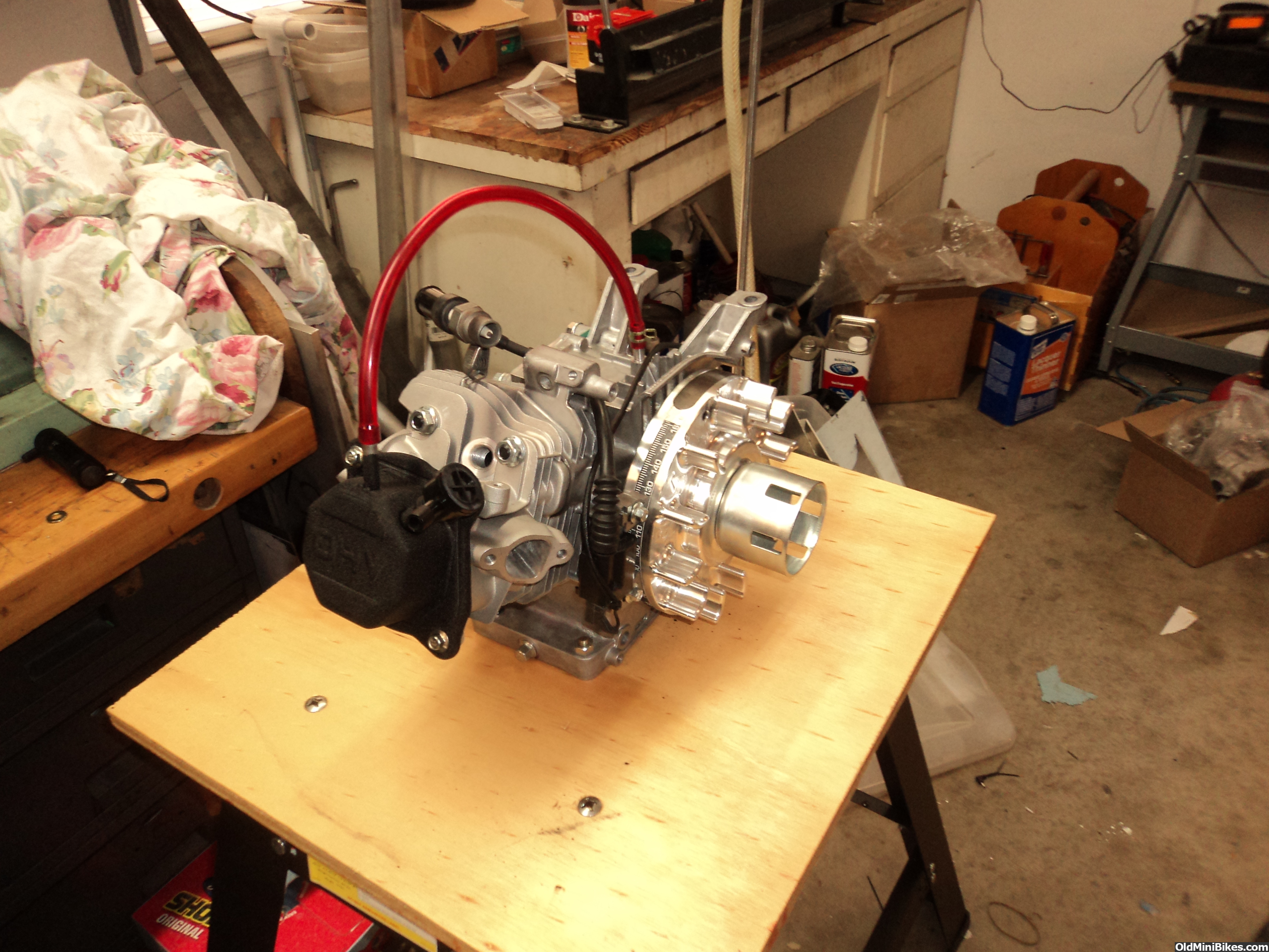
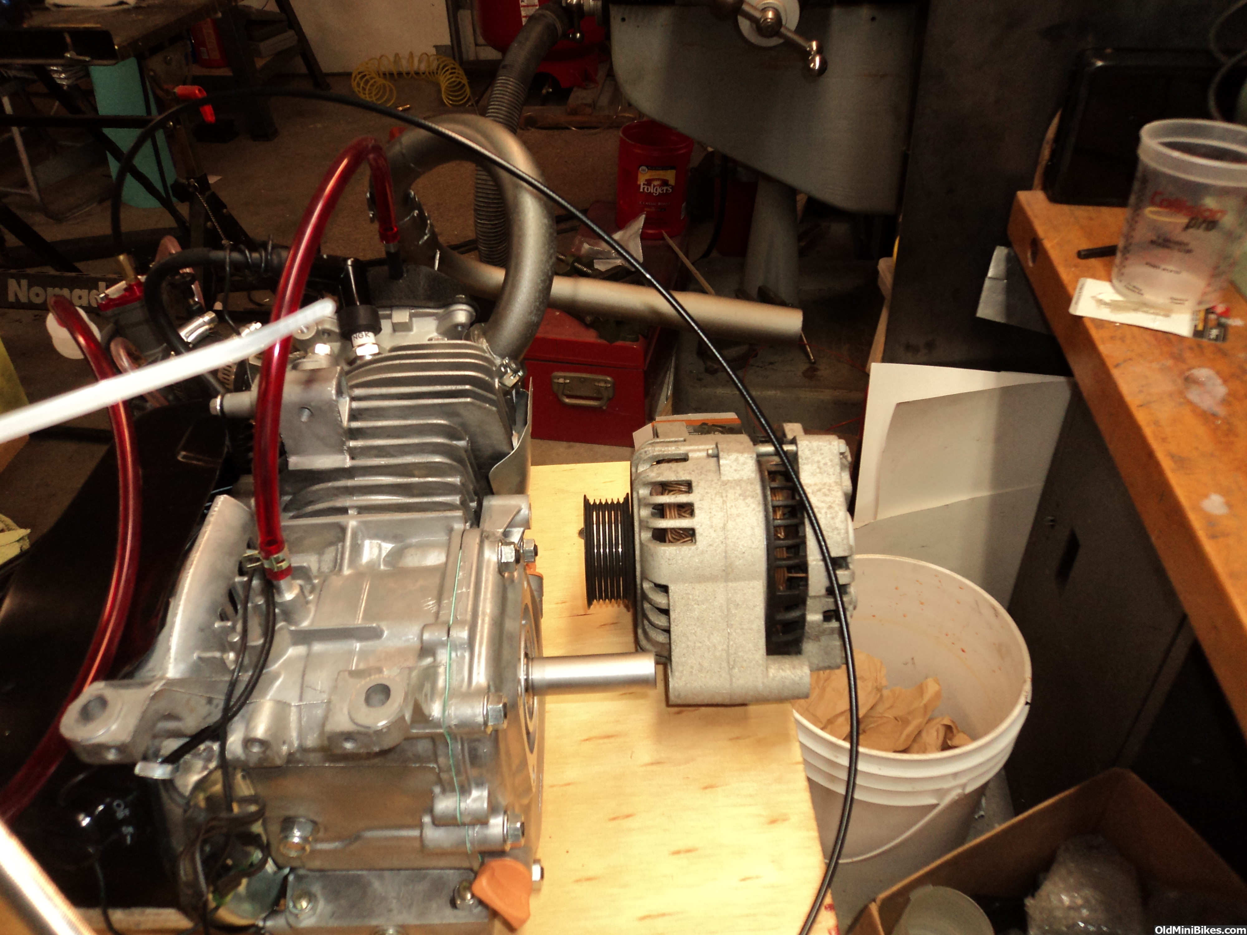
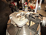
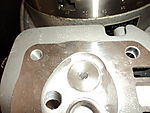
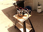
Mounted it on the test stand and did a quick fire with starting fluid man the dam thing is loud! This is the 14cc head (now 16cc) and the extra compression really gives it a crackle. I am thinking about mounting an alternator on the test stand and getting some high wattage resistors with some switches to make it a variable load so I could do some break in on the stand. I am figuring a 100 watt alternator under full load would take about 4HP to run it. I would not load it that much but it would at least allow more cylinder pressure under load to help seat the rings. Has anyone tried it?? I am also working on the next 18cc head. I have installed the 32mm seat and am now deshrouding on the mill as it does a much neater job that I have been able to do with the hand grinder.


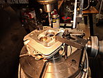
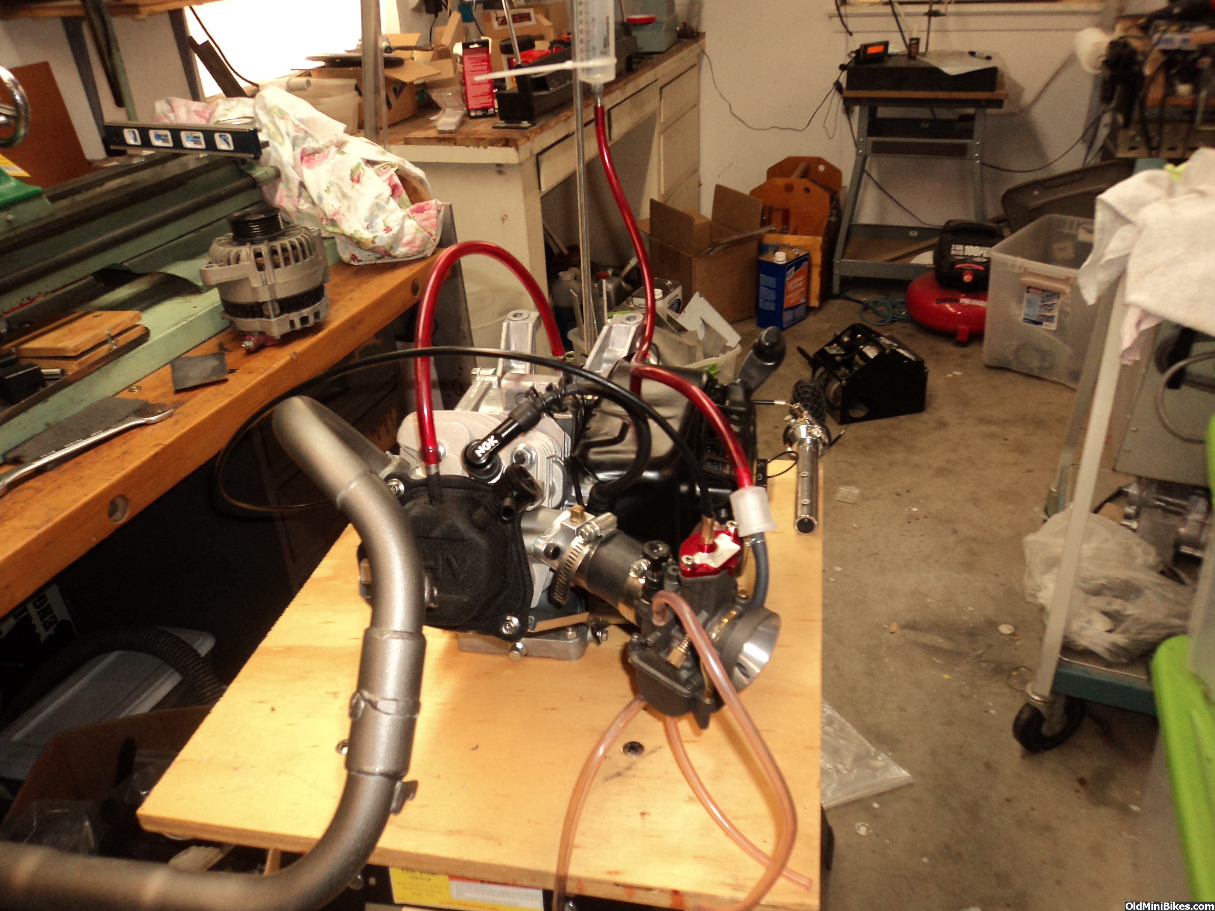
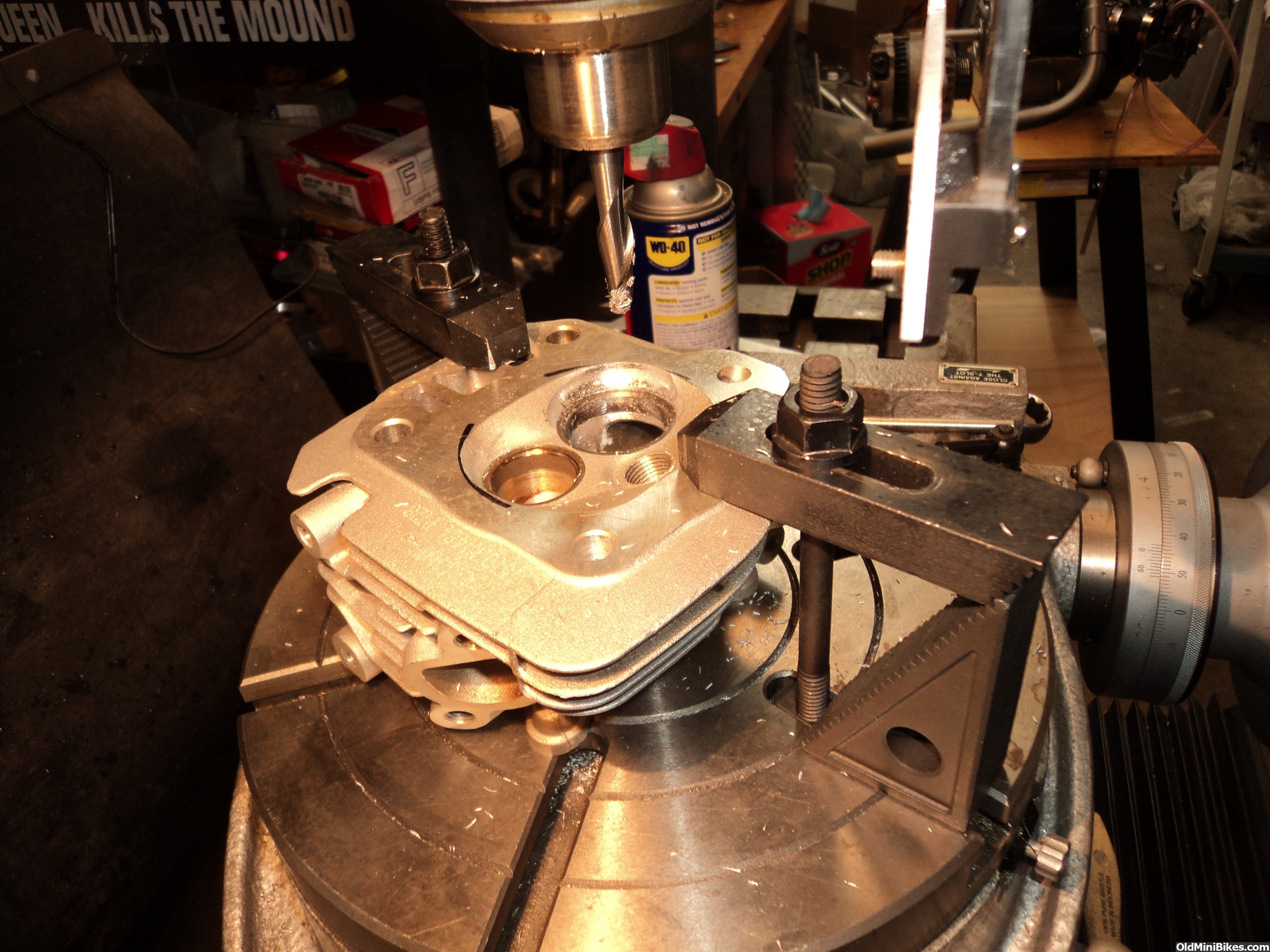
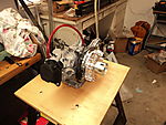
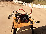
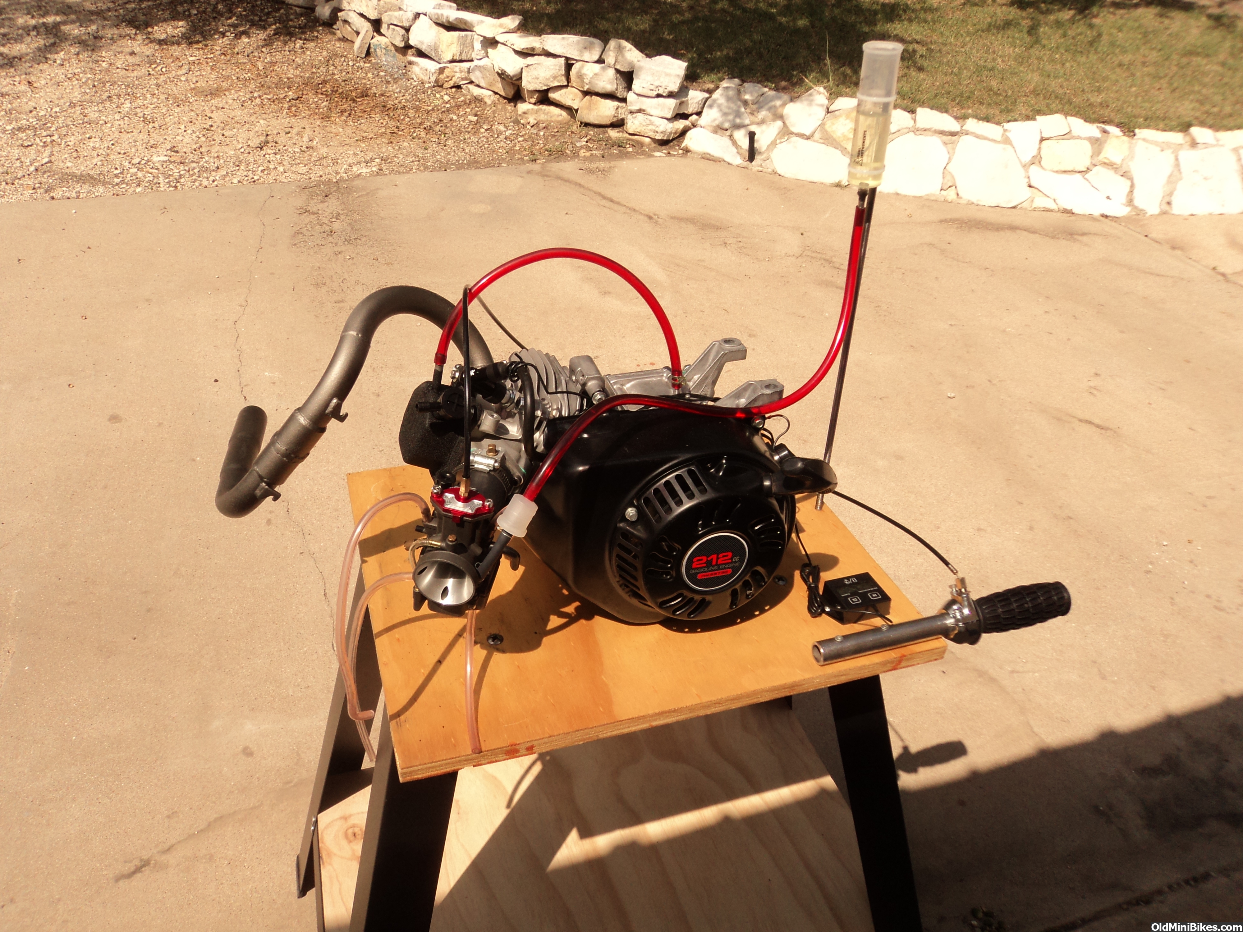
Well its been a while since the last update so here goes, finished the motor a while ago and then was away on a cross country trip for a month. So I started it up today with the first of the three big valve heads. This one is the 14cc head with a 32/25 valve size and also the first time using the 26mm Nibbi carb. Started it with the installed jets 38P and 110M and it fired right up and after some adjustment idled and picked up just fine. I decided because of the high compression (11.9 to 1) I would richen it up a tad so I had a 118 main and a 40 Pilot. Still runs just fine revved it up quite a bit to see if the power jet ever drew gas and it did not. I will have to watch for it while riding I guess but it never pulled any fuel into the tube. Anyway it sounds really crisp. Next head is the early Honda design with a really nice chamber with two equal squish areas and I have installed a 32mm seat and unshrouded the seat area in this picture next is porting and testing.
 [video]https://www.oldminibikes.com/forum/photopost/showphoto.php?photo=143105&title=non-hemi-pred&cat=5114[/video]
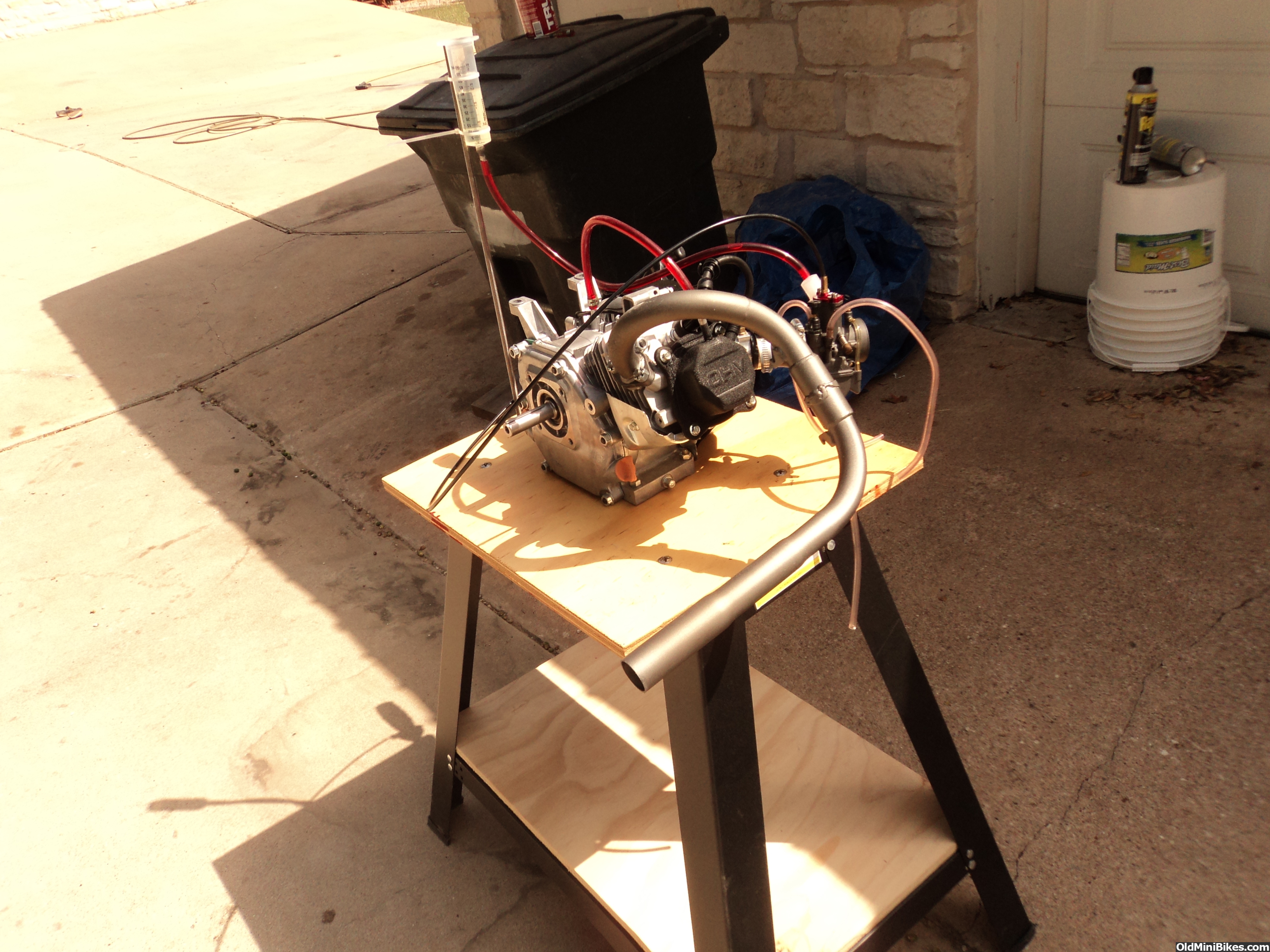
Mounted it on the test stand and did a quick fire with starting fluid man the dam thing is loud! This is the 14cc head (now 16cc) and the extra compression really gives it a crackle. I am thinking about mounting an alternator on the test stand and getting some high wattage resistors with some switches to make it a variable load so I could do some break in on the stand. I am figuring a 100 watt alternator under full load would take about 4HP to run it. I would not load it that much but it would at least allow more cylinder pressure under load to help seat the rings. Has anyone tried it?? I am also working on the next 18cc head. I have installed the 32mm seat and am now deshrouding on the mill as it does a much neater job that I have been able to do with the hand grinder.
 ut. Just be far away when that 10 pound mass of steel decides to become a 7000rpm projectile!!!
edit: Why not just ride the thing slow?
Sorry I posted wrong pics. I think you mean 100 AMPS at 100 AMPS the alternator will take 2HP enough to add a good load but I did not peruse it as I have too many other projects to get to. I would have had to come up with varying resistance as well as add a battery to get the alternator going and vary the load.
Sorry I posted wrong pics. I think you mean 100 AMPS at 100 AMPS the alternator will take 2HP enough to add a good load but I did not peruse it as I have too many other projects to get to. I would have had to come up with varying resistance as well as add a battery to get the alternator going and vary the load.
https://www.digikey.com/products/en/potentiometers-variable-resistors/adjustable-power-resistor/83