hemi head rework

#21
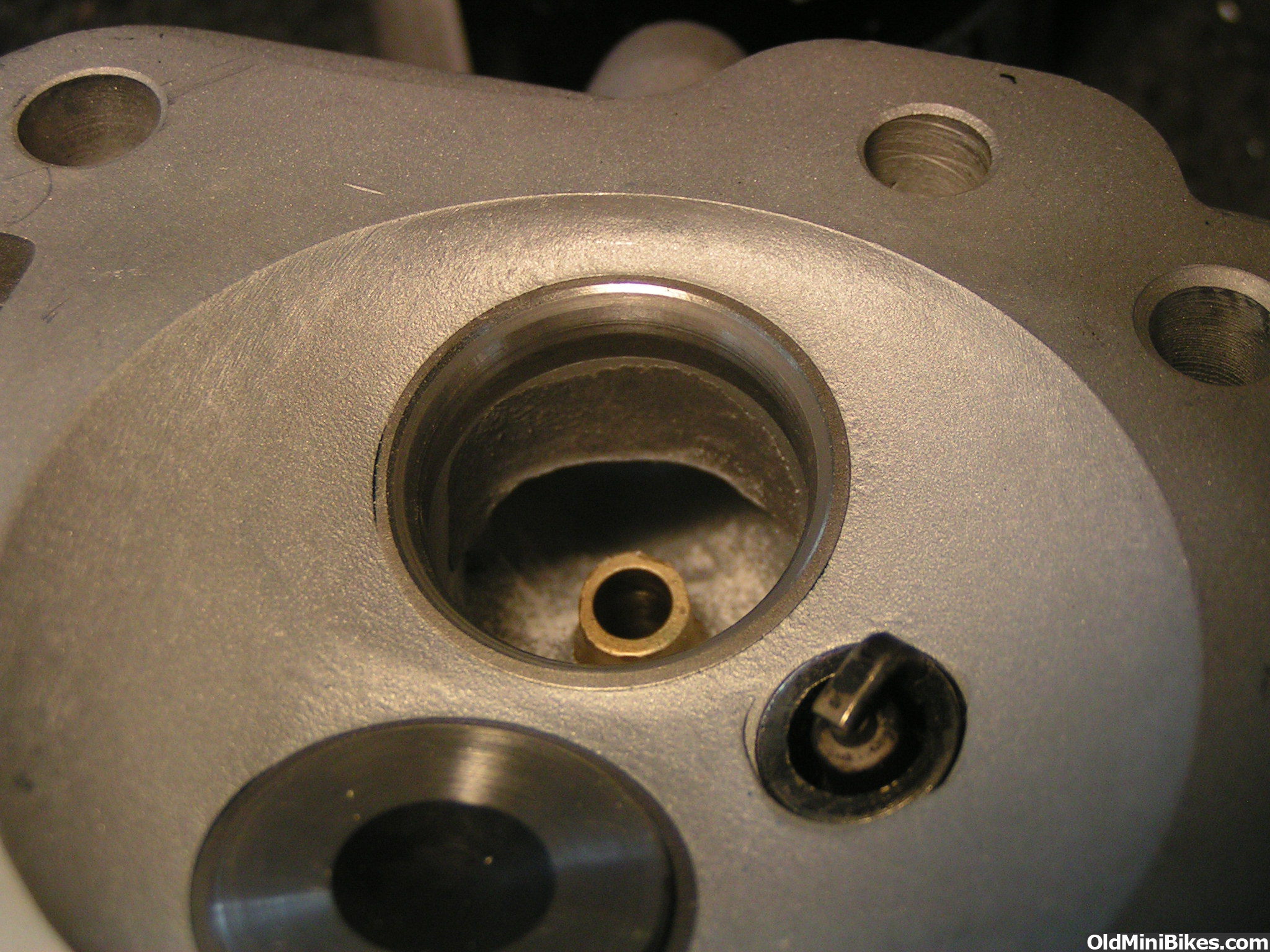
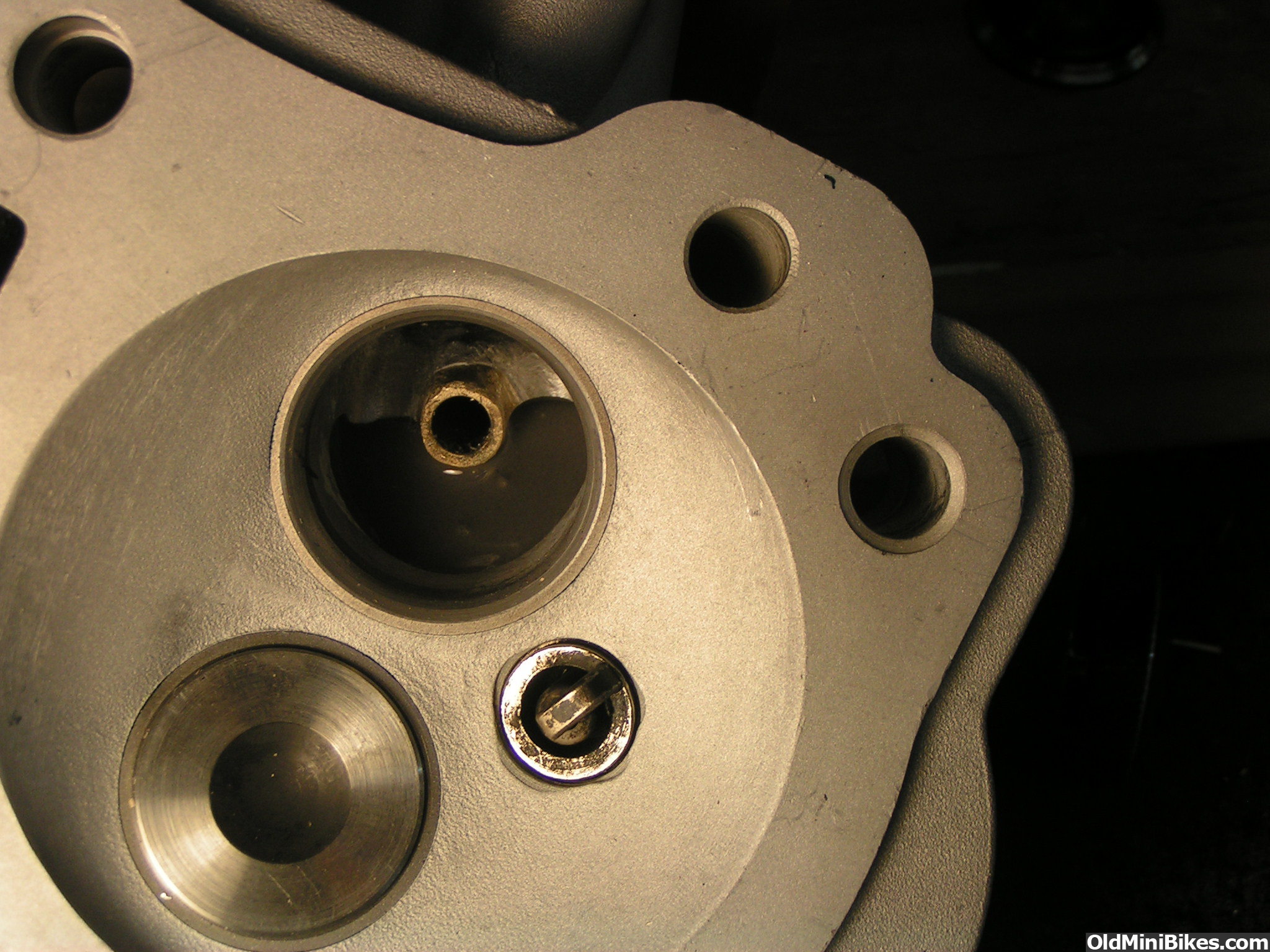
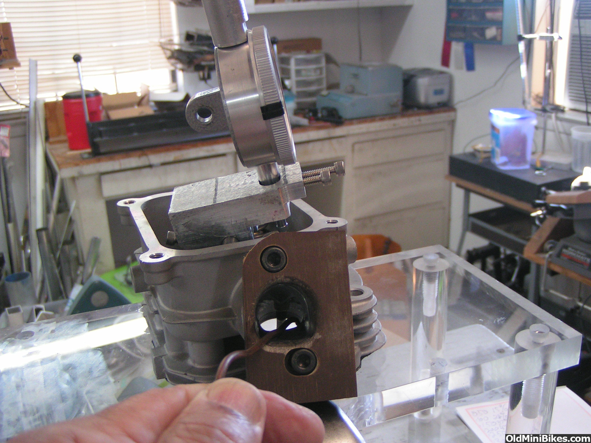
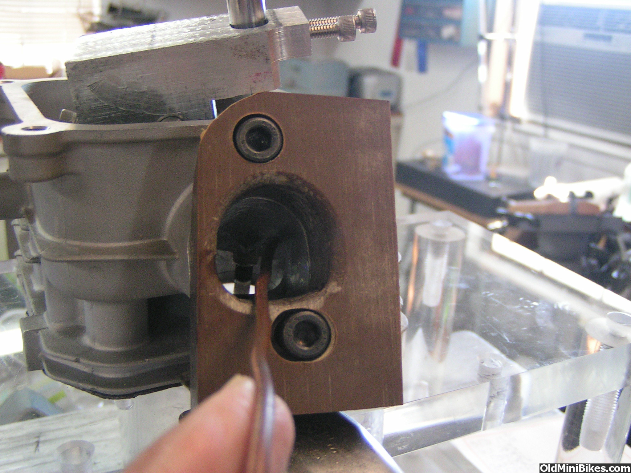
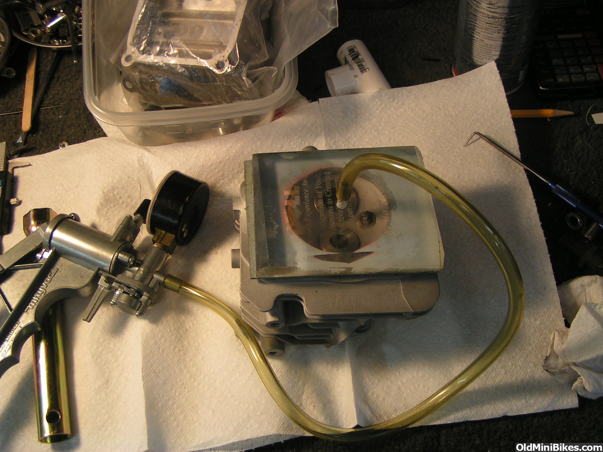
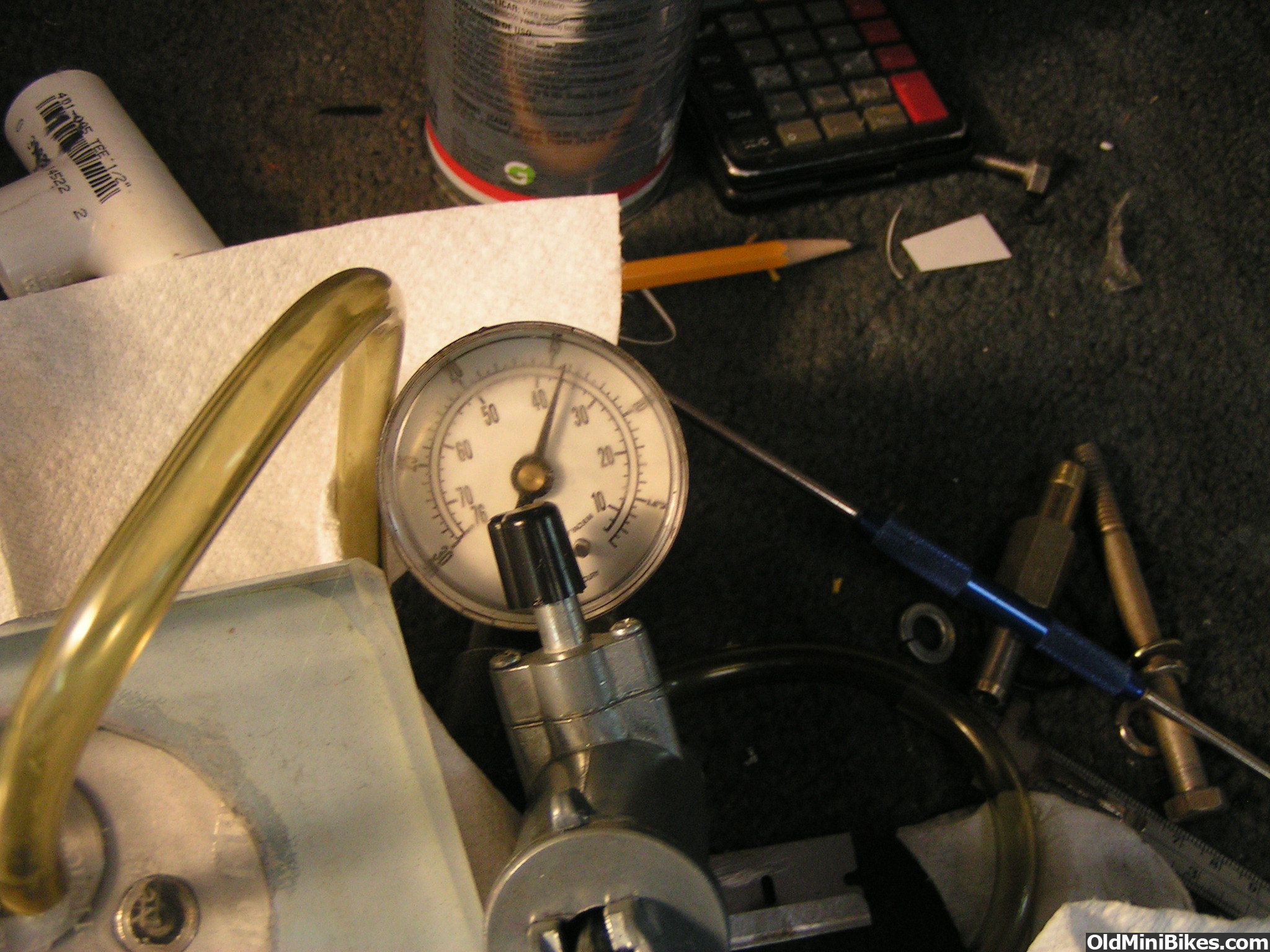
Well finished the valves and seats, 4 angles on intake and 3 on exhaust. Looks like I could open the throat a tiny bit more but installed valves with checking springs and put it on the flowbench. Results were pretty bad. The last measurement that says .450 lift really wasn't it was still at .400 but I was using a flowball to see where there were problems with the port and it was the floor right before the shortside turns the ball increased flow about 5 CFM. Looks like I need to rough up and add some epoxy to the port floor and raise it up before and into the shortside.

 
#22
I know the guys on the kart sites are getting 90-113cfm out of the Hemi head,
And with some epoxy on a Honda head they are getting 98-107cfm...

Best I can do on a 14cc head is 75-78 cfm with a 27mm valve...

Best of luck to ya!!!
 
#23
They are using 32mm valves and a floating depression bench so at higher lifts are not actually using 28" h20 but a lot less and letting software correct to 28" so i have no idea what it would test on mine. I did test misfits 32mm head and at .350 lift got 88 cfm. His setup coil bound at .360 so I never got to test at .400. His head had a stock sized runner as well.
 
#24
Another note on flow is I have flowed a number of heads here and the best flowing 28/28.5 head I have is a old MDB Honda head which was before they were D port heads and although he opened up the bowl and runner it still had a very high velocity in the port as it was not enlarged too much. As I got it with no valve guide showing in the roof it flowed 81CFM and with new guides and valve job and going from a 28mm to a 28.5 valve was able to get 84CFM even with the guides in the port (they were tapered a lot however. The next best head was a Clements head that flowed 75CFM on my bench. One thing I did notice with the MDB head is he removes a lot of the short side and by accident I found when the vacuum was increased to around 30 or more inches I started hearing a god awful noise in the intake and the flow and vacuum reading was jumping around. I suspect that at higher velocities the port was becoming turbulent and the air stopped going around the short side area and was just going around the back of the valve to the long side. Anyway I am usually able to get 70 to 75 cfm out of a regular non hemi head without epoxy and just bowl work no enlarging of the runner except maybe a half inch up from the bowl. I just need more experience with the hemi. I have the short side filled now and will work on shaping the radius but with it higher and if it does not get to at least 75 CFM on my bench I will widen the walls and see if that helps. I was trying to keep the port offset so I still have some swirl as I did not weld the head to add squish.
 
#25
Well I filled up short side then put a nice radius on it but left it a bit high. Bench showed a loss of about 10 CFM, using the thread wand I could see thread following short side so I knew radius was good so I went back and lowered it a bit and picked up a bit of flow but still less than before filling. I used the smallest flowball I had and found a corner where flow picked up. I added some clay and flow was back up so I lowered short side in that corner and now I had around 71CFM. I thn saw putting the ball behind the guide picked up a bit so now I am filling the backside with epoxy and when it hardens I will shape it so the port long side has a nice radius. The more you learn about this stuff the less I realize I know. When someone says they can look at a port and tell if it flows good I am not so sure.
 
#26
Those photos pop and all kinds of great info here ( thanks for sharing )

My eyes were drawn to the bowl where you added the epoxy...

Next thing is the raised runner floor.
How thick is that ?

I see the attempt to keep the swirl going too.

How much metal do you have left to pull down the bowl to compensate for the raised floor?

And how much can you widen the throat and still have some of the swirl?

Side note:
Welding did not lead to any trouble with my seats.
 
#27
First two pics show the original epoxy fill about half of the port at the bowl tapering down about 3/4 of a inch into the runner. 3rd picture is where it is now a lot of it was removed then after flow testing more removed on one side and re radiused. Now I am waiting for the new epoxy to dry. The head unmodified had a LOT of swirl, I have a 3/32 welding rod with 5 strands of 3 inch thread and it would always go right to the left and around the valve not matter how far right you put it. The whole port runner was offset to the left. Now the same thread tool follows the short side so I have for the most part ruined the swirl. I am going to try to reshape the new epoxy on the long side to try and get some back. you cant enlarge the right side too much or you will cut into oil drain hole. After I am done I will make a new rubber mold to compare them. This engine is running one of isky's 330 lift 230 degree duration cam, basically a hi lift black mamba jr. Because its a hemi I wanted to get hi lift but at the time I started there were no hi lift rockers.
 
#28
Tim ground me 290 lift 246 duration that's been sitting around for this.
I was always afraid of the clearance issues.

You think there is much to be gained with trying to fill and re-curve the exhaust?
Can't eat when your bound up and the same would seem to hold true to engines.

I eagerly wait the casting of the port shape.
I can't flow my head, but maybe I can copy it to some extent ( I think you are on the right track )
Darn good show man!
 
#29
I'm using epoxy so no go on exhaust. The exhaust flows plenty relative to the intake on these so you don't need to go too far on them. I did some more shaping then testing on the flow bench. While it is OK I am a bit disappointed as I would have expected more max flow because of the more favorable downdraught angle with the hemi. Anyway I did some port velocity measurements using just a straight copper tube (I can't see spending a couple hundred bucks for a small pitot tube so this tells me where the speed is fast and slow so works just fine other than I have no way of calculating FPS. Anyway the port floor was pegging the vacuum meter at 50" of H20! more on the right but almost as fast on the left, while the roof was around 30" which is what I would expect. So I started assembling the head and checking seat pressure and decided I needed to take apart the intake and make a mold to show you guys what was done and boy was I surprised when I pulled it out what screw ups I found that you can't see looking into the port! I could feel it on the floor but not see it on the wall. Here are some photos of the head, the flow test, velocity probing and I just poured another mold to see how much I fixed the screwed up floor and side wall, also contured the roof top epoxy a bit more.

 
#30
The last photo on the above post shows the mold and the restriction in the port where I did not remove enough epoxy which is chocking down the port and why velocity was so high. I am surprised the air still went around the short side like that.
 
#31
Finished, although I could probably get a bit more my low lift flow is starting to drop so I will leave it as it is. It now has enough flow for the cam I am using and very good port velocity. Here is the final flow figures. The exhaust I flowed backwards as I was too lazy to reverse the motor box. The baseline exhaust readings were flowed blowing thru exhaust which is the correct way. The last mold was with the floor fixed from the middle mold and then I looked at the last one as saw a couple of areas in the bowl around the guide I massaged a bit.

 
#32
The final shape is impressive.

I am extremely impressed with the short side work you did and how it came out.

Also the bowl work you did and how you feather the guide is very nice.

Nothing you did is greatly surprising since the final shape is more or less what I expected.
But what is impressive is the fact you showed how it was done an back it up with numbers.

PLUS the castings you made.
BRAVO....

Can I ship you my head now for work lol......
One of the best threads and most informative reads here in a very longtime!!!!
Worth a sticky too!
 
#33
I also been following this thread and it is very informative . I have a hemi head that I'am thinking about starting on soon . Thanks OLE 4 for the information and all the detail .
 
#36
I cut the final mold across at the narrowest point to get the cross section area and came up with the same .543 (give or take a slight amount) as the original port was! So using a figure of 137 CFM per square in. (Max flow for a square inch area with a CD=1 is 147CFM) According to darin morgan a efficient port will flow 137CFM per SQ in. So using 137 x .543 = 74.3 cfm about what I got so I am feeling good!!

 
#37
Next I need to set installed height (.850 or so with 37 LB springs) machine down spring shims to fit in the spring pockets I cut for the 37 lb springs, check seat pressure and do about a .007 cleanup mill as the head was heated and cooled a few times taking out original guides and installing the bronze guides.
 
#38
Finished up milling, shimming, test valve seal and seat pressure. One issue with the longer valves and lashcaps is the retainer to rocker arm clearance with valve closed is tight need to put the head on the motor with stock pushrods and check for room for adjustment, rocker arm geometry, and valve to piston clearance with the .330 lift cam.

 
#39
Put the head on without a gasket and clayed piston to check valve to piston clearance with the isky .330 lift cam. Still had plenty of clearance .090 on intake and .125 on exhaust. Rocker arm geometry is not too good however. I made up the 1/4 inch pushrods a bit too short and the wipe area on the lash cap is not centered it is more toward the rockers. The valves are around .200 longer than stock which does not help. I have a bit of room between lash cap and retainer/locks so I will take off .040 off of the valve tips, and also mill the head .035. Adding a .009 head gasket takes that away but I should get closer. I also ordered more make to order pushrods from isky so I can make another pair slightly longer.
 
#40
Do I see the spring pockets?
How deep did you go?
Maybe its an optical delusion on my part but I also see shims too.

I wonder if you could shorten the lash adjusters to remove some of the unsprung weight ( if there is in point too it as well )
I just don't like that part of the stock rocker
 
Last edited:
Top