tecumseh-ohh build
- Thread starter delray
- Start date
- Tags build tecumseh-ohh


I will be running a different flywheel for this project and wanted to get away from the cast steel flywheel(heavy) I could of look into modifying it.
I have seen vkemotorsports lighten them up little and spin over 7000 rpm's. for me I just want the motor to spin as quick as possible from one point to another in 125 ft and under 4 seconds. one option I may have in the future would be a animal billet flywheel with adjustable timing and use the pvl coil. now that I have a Indexing Dividing Spiral Head 3-Jaw Chuck I could look into making the adjustable hub. for now I am going with a Tecumseh aluminum flywheel for testing purposes. very happy in the pass too with using one on my hs-40 build that spins over 7000 rpm's same kind of flywheel material they use on there AH58 2 strokes that spun well over 8000+rpm's.
first drill deeper into the mounting holes. this will allow me to come back later and tap the threads.

and then knock down mounts. this will allow the new flywheel to align with my hot coil.

notch out the center. this will allow the coil it self to fit correct

re-tap the holes


flywheel I found that will work on a ohh I stumble across when I was doing some research on flatheads made in Italy and weird thing is I purchase a Italy made engine at a local swapmeet years ago and just sat on it. not knowing this a full bearing crankshaft motor with a steel sleeve 2.795 bore and use a aluminum flywheel that was very similar to the vertical engines use. but this flywheel had the mags casted into the flywheel and not mounted /pin on the outside flywheel and the casting was a lot like the older flywheels where casted. very smooth with no casting flash/lines in them.
here is the Italy Tecumseh.

i have found this same flywheel couple times on ebay and looks like it may have been use on some vertical flywheels. but you do have to watch for couple things. first the way the mags are mounted,casting and the keyway must be the same. i have seen this part little different in some vertical engines.
here is some more weird stuff to look at. on a newer flathead that only comes with a cast iron flywheel and electronic ignition has this little extensions on the coil mounts. if a guy took this off a aluminum flywheel would match up to the coil?

I have no problem with spinning this flywheel to the moon for only 4 seconds or so or less with a good balanced torque converter or clutch with a third support bearing bracket like the jr drags use. I would never try this with a 20 or 30 series driver. the parts are way out of wack to spin high rpm's with a light flywheel.
with a light flywheel it makes the engine spin very quick and fast. works good for my type of application. for example I would never use it gokarts racing or similar conditions. for drags racing it works(light) for circle track .....no
if time permits I still would like to maybe make a animal adjustable billet flywheel work. I would have to make my own center hub to fit my tapered shaft. it is little more heavier. i could mill the fins off and lighten it up little bit. i don't really need fins to run the bike for 4 seconds down the track. i will have plenty of air going around it and though it.....lol

next was to make this a full roller crankshaft and for some of you guys that have followed my hs-40 build seen this done.
https://www.oldminibikes.com/forum/index.php?threads/hs-40-build.161335/
building the hs-40 motor was all tied in with this ohh motor. see if these mods would work and how much punishment it could go through and it did. exceeding sometimes over 8000 rpm's and long time distance.
I only have some previous pictures from my last build on how I machine the crank for the roller setup. some reason I didn't take any pic's of my ohh crank being done.


harden sleeve that will need to go on.

pretty easy to do. just kept the clearances couple thousands bigger on the crank and then froze the crank overnight and then the next day I setup the crank in the vise vertical and heated the sleeve and it drop right over. I also held it down for couple minutes to makesure the sleeve would not push up as it was cooling down of the crankshaft

i really like my 4 jaw chuck. i got the crankshaft spot on when turning it down.
also i had the crankshaft sent off to be re-welded on the rod journal. i well being making it into a stroker crank. going from a 1.938 to a 2.00 stroke.
here is the engine block side of it all.
the block will need to be machine out for the roller cage setup.


356 dyno cam will also be getting a compression release setup. before I can do that I will have to open my jeg some more so the cam lobes will clear.
jeg was originally setup for just my 245 dyno cam. now that I am going to a much larger lift I will need to open the hole some more.


jeg was originally setup for just my 245 dyno cam. now that I am going to a much larger lift I will need to open the hole some more.


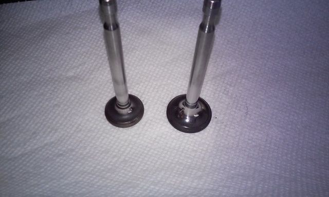
there was not much to clean up for the valves and head. i did clean up the bowls. only ported the bowls into start of the runner. it was not hard to figure out what needed to be clean up. both the intake runner and exhaust runner it self i did not touch. they look to have plenty of airflow.
factory valves are small, but they still proved to flow good power for this project build on a minibike.
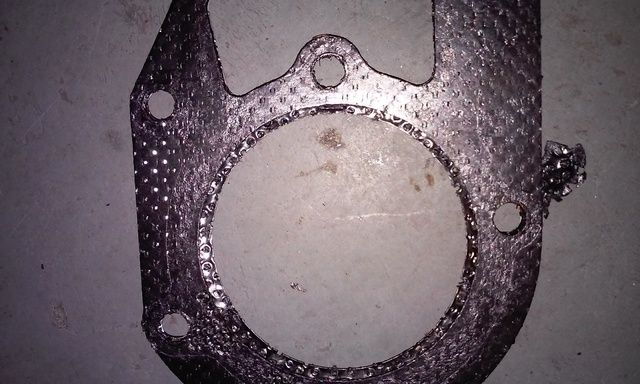
before bolting the head back on . i decided to measure thickness of the new and old head gasket and they came out to be .040
i also found some info on the internet saying the gasket was .040 thick.....:thumbsup:
i wet ahead and installed the head without the gasket and found that the valve train look good. everything was lining up real good still.
so at that point i wet ahead and milled .040 off.
lots of room for bigger valves. maybe next project.....:smile:
factory valves are small, but they still proved to flow good power for this project build on a minibike.
before bolting the head back on . i decided to measure thickness of the new and old head gasket and they came out to be .040
i also found some info on the internet saying the gasket was .040 thick.....:thumbsup:
i wet ahead and installed the head without the gasket and found that the valve train look good. everything was lining up real good still.
so at that point i wet ahead and milled .040 off.
lots of room for bigger valves. maybe next project.....:smile:
Why is this blurrrrrry
fourtogo, if there is any pictures you would like to see clear just let my know what page they are on and PM me and i will try to dig them up for you.
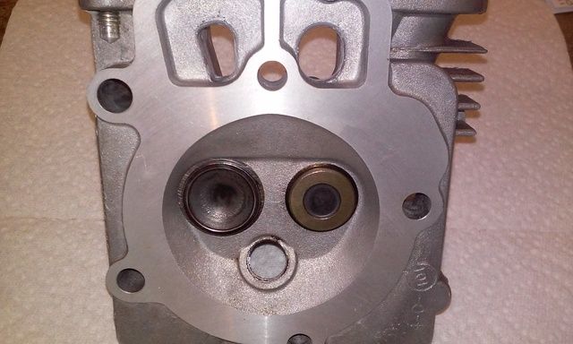
when finish with the head I still had room between the valves and even the valve seats didn't touch each other. running a 32 intake and 28 exhaust.
i end up cutting a good amount of radius around the valves and with cc'ing the head out and with my 2.910 bore/milling the head and stroking crank my compression came out about 12:1
next to a stock ohh head.

i end up cutting a good amount of radius around the valves and with cc'ing the head out and with my 2.910 bore/milling the head and stroking crank my compression came out about 12:1
next to a stock ohh head.

when finish with the head I still had room between the valves and even the valve seats didn't touch each other. running a 32 intake and 28 exhaust.
i end up cutting a good amount of radius around the valves and with cc'ing the head out and with my 2.910 bore/milling the head and stroking crank my compression came out about 12:1
next to a stock ohh head.
i end up cutting a good amount of radius around the valves and with cc'ing the head out and with my 2.910 bore/milling the head and stroking crank my compression came out about 12:1
next to a stock ohh head.