OK ... No heavier than 22# with stock retainers ... Cl1 is stock lift with more duration ?
valve lash caps are used for correcting valve train geometry.. most of the valves out there are too short and need to be longer. you can sink them in the seat but you may get low lift valve shrouding which impeads flow. to get your geometry correct use a degree wheel and a dial indicator on the valve retainer... zero the dial when the valve just starts to open rotate the engine forward till the valve opens all the way to max valve lift. mark max lift. rotate the engine backwards past the opening point and go forward again till you reach the halfway point in between the open and max lift marks on your degree wheel. this should be half your lift. at that point you should have a 90 degree angle between the rocker and pushrod.. meaning half the lift is over and half is under the rocker. if the valves are too short you can put valve lash caps on and or make the push rods shorter as long as you have the 90 degree angle between the pushrod and rocker at half lift your good..hope this helps
valve lash caps are used for correcting valve train geometry.. most of the valves out there are too short and need to be longer. you can sink them in the seat but you may get low lift valve shrouding which impeads flow. to get your geometry correct use a degree wheel and a dial indicator on the valve retainer... zero the dial when the valve just starts to open rotate the engine forward till the valve opens all the way to max valve lift. mark max lift. rotate the engine backwards past the opening point and go forward again till you reach the halfway point in between the open and max lift marks on your degree wheel. this should be half your lift. at that point you should have a 90 degree angle between the rocker and pushrod.. meaning half the lift is over and half is under the rocker. if the valves are too short you can put valve lash caps on and or make the push rods shorter as long as you have the 90 degree angle between the pushrod and rocker at half lift your good..hope this helps
Is there a way to do it with out the degree wheel? Can I just use something to mark the valve tip, adjust valve, rotate motor and see were the rocker is riding on valve. I just see a lot of people on line saying to run the lash cap on intake. Should I not unless its needed?
if you look at the rocker and mark the pto shaft with a sharpie exactly when it starts to open then mark the pto at max lift.. measure the distance between the two marks and that should be real close to half lift. use the clock method to bring the engine to half lift and check the angle of the pushrod to rocker..you use lash caps if you have to. don't use them just because everyone else does and not know why. if you need to talk to me directly about the geometry let me know
Is there a way to do it with out the degree wheel? Can I just use something to mark the valve tip, adjust valve, rotate motor and see were the rocker is riding on valve. I just see a lot of people on line saying to run the lash cap on intake. Should I not unless its needed?
[MENTION=55149]super nate[/MENTION] great description of checking valve geometry.
K I will buy a degree wheel and check valve geometry. I need to learn to degree a cam. I just installed the cam in my truck and would have liked to degree it when I did it as it was a custom grind. This will be good practice for me. Going to have to buy a few extra tools I need anyways. I would rather be an engine builder and not just an engine assembler.
if you look at the rocker and mark the pto shaft with a sharpie exactly when it starts to open then mark the pto at max lift.. measure the distance between the two marks and that should be real close to half lift. use the clock method to bring the engine to half lift and check the angle of the pushrod to rocker..you use lash caps if you have to. don't use them just because everyone else does and not know why. if you need to talk to me directly about the geometry let me know
Would a thicker head gasket also help correct a short valve like say a .045" thick gasket?
So to make sure I am getting this right. Turn motor tell I can see valve move. Mark the block using a marker or something. I am guessing I would use the edge of the key way as the reference. Turn motor tell valve closes. Find the middle between the two marks. Put shaft at middle and make sure the rocker is in middle of valve stem and if rocker is too far in than use lash cap. If rocker was too far out I would need a longer push rod correct?
Would a thicker head gasket also help correct a short valve like say a .045" thick gasket?
Would a thicker head gasket also help correct a short valve like say a .045" thick gasket?
Here:
ARC timing
At 15:00 ish he start talking about using the degree wheel to set timing. Going back and reading it does sound like super nate is saying to mark the crankshaft :shrug:
Obviously I need to be educated on this as well. Following along.
Last edited:
Here is the dial indicator I have saved. I dont have a head fixture to compress the springs, increase lift. I have seen quite a few setups though, mostly homemade.
Dial Indicator
Dial Indicator
I have the PDF I can email to anyone who wants to print it. And no, you don't mark cranks and blocks, you simply do the math.
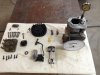
Here is a photo when I was indexing an unknown cam in a Raptor I. In this instance, I was getting crank angle at .050 lift, because in most cases, that is the number used by the grinders. That number will indicate how your cam lobe centers are set up, as well as ramp slopes, and of course max lift, which seems to be what everyone focuses on, because they're too lazy to put a degree wheel on. But hey, that sells cams, right?")
Shoot me a PM with your email address, and I'll send you a PDF file you can print of a degree wheel.
Here is a photo when I was indexing an unknown cam in a Raptor I. In this instance, I was getting crank angle at .050 lift, because in most cases, that is the number used by the grinders. That number will indicate how your cam lobe centers are set up, as well as ramp slopes, and of course max lift, which seems to be what everyone focuses on, because they're too lazy to put a degree wheel on. But hey, that sells cams, right?
Shoot me a PM with your email address, and I'll send you a PDF file you can print of a degree wheel.
Here is a pretty cool setup for clones. I imagine one could be made fairly easily, if you have the tools.
EZBore Bracket
EZBore Bracket
Last edited: