Powell in need of serious help

#21
Very nice rides. Even the roller looks good.

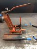
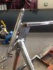
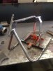
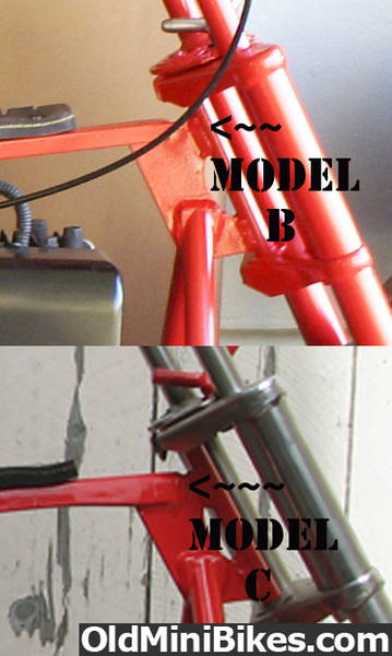
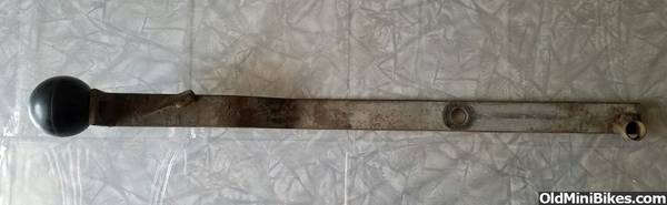
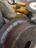
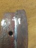
Ok here is what I found after taking the wire wheel to the frame. The frame was stretched. Exactly 2 and 3/4" It was very evident on the top tube, but once you looked closer on the bottom tubes, the different OD was easily seen.

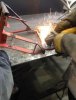
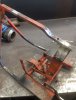
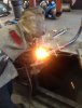
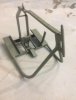
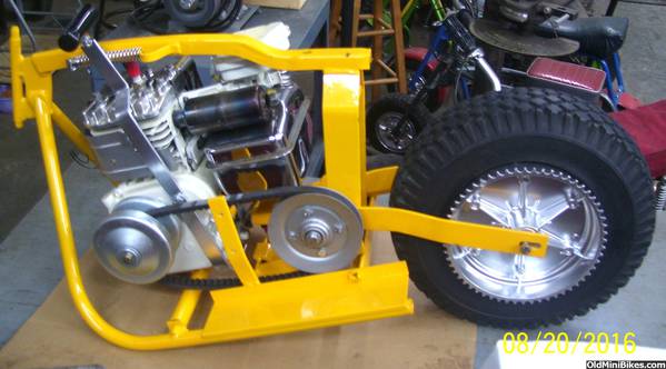
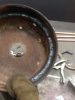
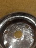
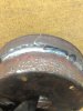
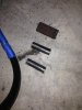
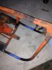
I went ahead and cut into last night and removed the slugs that were used for the stretch. This morning, I took the freshly beheaded Powell to my welding buddy, Mike.
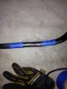
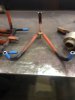
 IMG_4198.JPG IMG_4201.JPG IMG_4202.JPG IMG_4209.JPG
 
#23
The ugly welds were cleaned up and repairs were made. Also removed the large washer that was used a gusset on the inside the headtube. The frame appears correct comparing it to the example pics posted.
 

Attachments

#24
T-Town or OND can you post a close up of the pin/dowel that is on the front of the motor mount. Also needing measurements on the two pivoting straps and shifter arm. Any help would be appreciated.
 
#25
T-Town or OND can you post a close up of the pin/dowel that is on the front of the motor mount. Also needing measurements on the two pivoting straps and shifter arm. Any help would be appreciated.
OND did not build a bike with a pivoting mount. As I said earlier, that style of mount changed with the E model to a standard flat mount.

Here is a link to a bike for sale about four years ago. In your search, look for model B, C, and D for examples, not the later bikes that I and OND have.

One more piece of advice that applies to any bike you're having to rework the engine mount: Rough in the engine, and establish alignment with the driven system with belt and/or chain, BEFORE welding the engine in place. You can not easily make the lateral adjustment with the driven system later. On a Powell, it is almost impossible.

Nice repair on the frame.
 
#27
Hey Dave my Powell is a 4141 D and it does have one form of the tilting engine mount. Mine has the shifter that runs up the left side of the frame also.


But I think his bike has the other type engine mount that still tilts....but the pivot point is in a different place. His frame looks to be just like T-towns Powell , hence the 3 holes in top of the upper bar so he can use his shifter with the rubber slotted holder.


r89b I don't have the measurements for those engine mount parts. But it doesn't look like it would be that hard to make. You have the engine for a template to make the mounting straps. As far as the pivot point your bike still has the hanger sticking out...you just need some solid rod with some small pieces of the correct size tubing. All though the exact measurements would be great to have....maybe T-town will chime back in. [MENTION=26855]T-Town Mini[/MENTION]
 
Last edited:
#29
Thanks OND. Yes I believe my frame set-up should look like T-Town's. Making the swivel mounts doesn't look too hard. The pictures you posted cleared up a lot of questions I had. Does the shifter rod bolt to the side of the engine and pivot on the bottom? I'm trying to make out the setup on T Town's pic, just not real clear when I expand the pic. I know you have a different model, but you guys have forgotten more that I know about minis.

Thanks for everyones help so far.

Joe
 
#30
I think some of the shifters bolted to the side cover at the bottom on one of the actual side cover bolts at the bottom....that's why at the bottom of the shifter itself has a short spacer welded on to it. I bent mine at the bottom to go under the engine plate and used a motor mount bolt .


If you notice the cup on the bottom of some of the shifters....its not drilled out....I think the cup slid over the lower cover bolt.


Last edited:
#31
Hey Dave my Powell is a 4141 D and it does have one form of the tilting engine mount. Mine has the shifter that runs up the left side of the frame also.
Ah, my apologies Eric. Thanks for squaring me away, and thanks for assisting roc89 in this. He's doing a great job, quickly. Good job all the way around. I should have kept my yap shut, but at least I got to post a photo of my over-restored garage queen. (that was a bit of jocularity)

Keep on kicking butt roc89. Great to have you and that bike here.
 
#32
No apologies needed here Dave....:thumbsup: and I tried to post a pic of your beautiful ride on here with mine....but all I could get was jpeg sizes.:wink:
 

T-Town Mini

Well-Known Member
#33
T-Town or OND can you post a close up of the pin/dowel that is on the front of the motor mount. Also needing measurements on the two pivoting straps and shifter arm. Any help would be appreciated.
The engine pivot mounts are made from flat stock with the following dimensions:
1" wide x 3/16" thick x 7 5/16" long

There are four 5/16" diameter holes... each centered 7/16" from the end and 9/32" from the edge.


The mount uses a rubber bushing inside 1" OD tubing as located in the photo:


The pivot mount is offset approximately 3/16" off center to the right hand side.
(photo perspective is looking front to rear)


The pivot mount uses round stock with dimensions as follows:

Overall length is 4 15/16" long with a 7/16" diameter center section measuring 2" wide. The remainder is stepped down to 3/8" diameter threaded for 3/8-24 NFT hardware.

The stepdown is used as a stop for the pivot mounts when bolted on with washers on either side of the rubber bushing. These measurements might have worked for the original engine options giving proper alinement for the drive sprockets. I suspect they may not be exact for all engine/clutch applications and according adjustments may be necessary.

If anyone has additional/differing information or notes any errors in my measurements...please correct as needed.
 

T-Town Mini

Well-Known Member
#34
Here's some photos of the gear shifter:


I'm not sure what engine it was made for originally (Briggs?)...it was modified as can be seen in the photos...and had been mounted on a Honda.

I hope this helps in fabricating the parts from scratch. Good luck.
 
Last edited:
#38
SNAFU part 2. The rear wheel. First 4 out of the six bolts broke flush with sprocket half of the wheel. I presoaked in oil and cleaned the best I could, even heated the bolts. The other half of the wheel with the brake lip was an even bigger issue. It was missing a crescent shape of metal, about 1/3 of the way around near the lip. The area was cleaned and welded. The area was carefully grinded and shaped. Not perfect, but night and day to what I started with. The broken bolts are next. If I can't extract them, I'll drill and tap for the next size up. IMG_4243_opt.jpg IMG_4245_opt.jpg IMG_4246_opt.jpg IMG_4247_opt.jpg IMG_4249_opt.jpg IMG_4257_opt.jpg IMG_4258_opt.jpg IMG_4259_opt.jpg
 
#39
IMG_4262_opt.jpg IMG_4266_opt.jpg IMG_4267_opt.jpg IMG_4269_opt.jpg Went to Austin this weekend for my birthday. Decided to pick up a couple birthday presents for myself.

Bought them from two different guys, but they must have been part of the same ugly seat gang. :thumbsup:
 

T-Town Mini

Well-Known Member
#40
SNAFU part 2. The rear wheel. First 4 out of the six bolts broke flush with sprocket half of the wheel. I presoaked in oil and cleaned the best I could, even heated the bolts. The other half of the wheel with the brake lip was an even bigger issue. It was missing a crescent shape of metal, about 1/3 of the way around near the lip. The area was cleaned and welded. The area was carefully grinded and shaped. Not perfect, but night and day to what I started with. The broken bolts are next. If I can't extract them, I'll drill and tap for the next size up.
View attachment 94055 View attachment 94056 View attachment 94057 View attachment 94058 View attachment 94059 View attachment 94060 View attachment 94061 View attachment 94062
That's going to look just fine after some powder coat. Nice save.
 
Top