My Heald Hauler
- Thread starter Piezak
- Start date
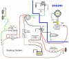
Here is my electrical diagram which I've put together. In each conductor in my diagram, where you see a little circle, that is a connection or splice. In a wire it is most likely a splice. The ignition switch has been replaced. It does not have numbered terminals, but is fine.
The battery is bad. It loses 3 volts in 3 days while being disconnected.
The Rectifier/Regulator was not outputing any DC voltage. I have a new one, but have yet to install it.
One thing I am unsure of, with the switch removed, I am getting continuity between the green ground wire and the green motor connection at the firewall and I am getting continuity between the green ground wire and the black starter solenoid wire at the firewall. This might be normal as they both involve coils.
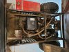
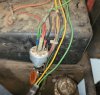
You can see the Disconnect Switch in a picture above. It is a good heavy switch. It was added as my step brother had issues with the battery going dead.
I am contemplating adding a diode and a fuse to the output from the Rectifier/Regulator so that I don't fry my new one now or in the future. Also while adding these components, I want to move the Rectifier/Regulator DC output from the Starter Solenoid to the battery (+). Once I have the charging system protected, I will purchase a new battery. I also plan to move the brake switch input power to an always hot (+) location as well. I appreciate any comments.
Thanks!
The battery is bad. It loses 3 volts in 3 days while being disconnected.
The Rectifier/Regulator was not outputing any DC voltage. I have a new one, but have yet to install it.
One thing I am unsure of, with the switch removed, I am getting continuity between the green ground wire and the green motor connection at the firewall and I am getting continuity between the green ground wire and the black starter solenoid wire at the firewall. This might be normal as they both involve coils.
You can see the Disconnect Switch in a picture above. It is a good heavy switch. It was added as my step brother had issues with the battery going dead.
I am contemplating adding a diode and a fuse to the output from the Rectifier/Regulator so that I don't fry my new one now or in the future. Also while adding these components, I want to move the Rectifier/Regulator DC output from the Starter Solenoid to the battery (+). Once I have the charging system protected, I will purchase a new battery. I also plan to move the brake switch input power to an always hot (+) location as well. I appreciate any comments.
Thanks!
Last edited:

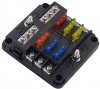
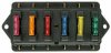
Change this. I received that fuse block and it wasn't water proof and also I could only have one power source be the input for all legs. So, I've bought another. This will allow different power source inputs as needed.
Scratch the diode. I am not going to use a diode. I don't want concerns with voltage drops.
Scratch the diode. I am not going to use a diode. I don't want concerns with voltage drops.
Last edited: