A-cat battery module

Minimichael

Well-Known Member
#1
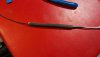
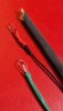
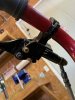
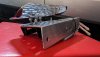
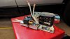
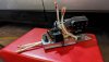
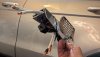
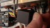
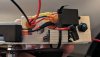
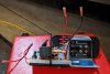
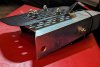
The new electrical heart of my Arctic Cats. Their tailpipes run under the right side of their seats and center bars, and this electrical assembly will mount under their left. That extra blast shield on stilts reaches out toward the tailpipe, to further protect the front of the battery pack from a pretty hot section of flex-pipe. The blast shield on the second bike's module is in a different position to fit that bike. The battery dock fits Milwaukee M18, for a low profile 18v charge stepped-down to 12v. Exposed wires are silicone/fiberglass sleeved. Components are currently in a zip-tied jumble of regulator, fuse, and relay, to keep them tucked in behind the module's firewall. But each one of them hangs from its own grommet hole in the switch box, for ease of access more than anything. Pairs of hot and neutral wires feed from both the front and side, while two relay wires feed backward.
 

Attachments

Last edited:

Minimichael

Well-Known Member
#4
Thanks! Here's the other one so far. On this one the side feed and the dock wires each drop from a grommet, which I like better, since the first one involves splices and more wire traffic. The close up shows the adjustable relay box, adjustable step-down converter, and fuse. Still gotta drill small access holes in the firewall to reach the convertor's adjuster screw.
 

Attachments

Last edited:

Minimichael

Well-Known Member
#5
Sneak preview as I continue wiring ...

The components worked individually on the bench, but I'm already seeing performance glitches with multiple turn signals hooked up. I think the relay needs a kick in the butt to get going, since it buzzes first before then starting to tick-tock. I had earlier adjusted the voltage down below 11 to temper an led headlight's glare...maybe that's it. Or maybe I need a condenser or capacitor to give the relay a kick? I also plan to mix led and incandescent lights and switches, but with very limited electrical know-how.

Plus I just noticed the rectangular headlight is halogen, and the chrome one might be also. Am I gonna start a fire in my dining room?
 

Mr. Pink

Well-Known Member
#6
I’m assuming that you have a second battery.
One in use while the other one is being charged.

To see if one or more of your components is drawing more current than your battery can handle, take your second battery and temporarily hook it up in PARALLEL with the first battery. That will give you twice the amperage while keeping the voltage the same. Then be sure that none of your wires or connectors are getting warm while in use.
 
#9
:D 
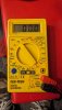
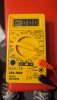
Well, I'm not really good at this kind of stuff, but I'm pretty confidant that your'e going to want to raise your voltage back to at least 12/12.5 volts and either lower the wattage on your LED's or shade them somehow to lower the glare. The coils on relays and such work just a little more efficiently at the upper end of their rated voltage range. More volts less amps = a little less heat. Even on the low volt stuff.
 

Mr. Pink

Well-Known Member
#11
Have you figured out what your total wattage will be with everything on?
See? I knew there was more to this. No, I haven't. I'll have to look back at the sites I bought stuff from I guess..
A $10 Harbor Freight multimeter will work in a pinch.
But the test leads and connectors are kinda flimsy.

A nice Fluke along with quality alligator clip jumper wires are a good investment.
 
#13
I use similar setups on various equipment, except I use RC car batteries, as I have piles of them, and they are cheaper than tool batteries.
I have digital voltmeters wired into each and every one of them. I can see voltage drop with each bulb I turn on, and if I had blinkers, I could see the voltage bounce with each blink. I know when my batteries need a charge at a glance, too.
 
Last edited:

Minimichael

Well-Known Member
#14
So, just thinking out loud here...seems the DCV scale will tell me the capacity of a switch (not real helpful) whereas DCA measures what a device is currently pulling. And I could bench test each device that pulls, and write it all down...and V • A = W, for each ....

I think I'm getting it.. and starting to understand I probably want bigger batteries than 2.0Ah.
 

Attachments

Last edited:
#16
To measure Amps, you need to be in SERIES with the device. That means disconnect it and put your meter in line with the device.
Voltage is measured in PARALLEL. Leave the circuit connected and just touch the battery terminals with your leads.

RC car batteries...
What sparkwizard says. ;) Also that 10 amp max rating is set in stone. There is an internal fuse.
 

Minimichael

Well-Known Member
#17
Thinking of going with something uncomplicated for a brake light switch. Two open wires sharing a raincoat, zip tied just inside the rear swing arm, and actuated by the brake drum lever. The extra zip ties heat shrunk along with the wires are for strength, but I'm hoping the tips poking out into those exposed wire loops might also encourage good contact and maybe even release.
 

Attachments

Last edited:

Minimichael

Well-Known Member
#18
To measure Amps, you need to be in SERIES with the device. That means disconnect it and put your meter in line with the device.
Voltage is measured in PARALLEL. Leave the circuit connected and just touch the battery terminals with your leads.

RC car batteries...
What sparkwizard says. ;) Also that 10 amp max rating is set in stone. There is an internal fuse.
Still reading up on electromagnetic forces, intensities and measures...

Real life testing will help, too
 
Top