before I begin this is what I currently am working with. I have a bike and a trike with torque converters and un governed modified engines and I'm trying to get the most speed out of my current setup. I already upped the engagement to 3100 using the white garter springs for the driver and installed the stiffer yellow spring in the driven on the stiffest setting. on both and I have a set of the lighter cast aluminum weights to try that I just need to order the correct springs for. I currently am useing the 6 inch drivens and may swich to the 7 inch at some point because I hear they allow the engine to rev better.
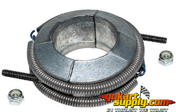
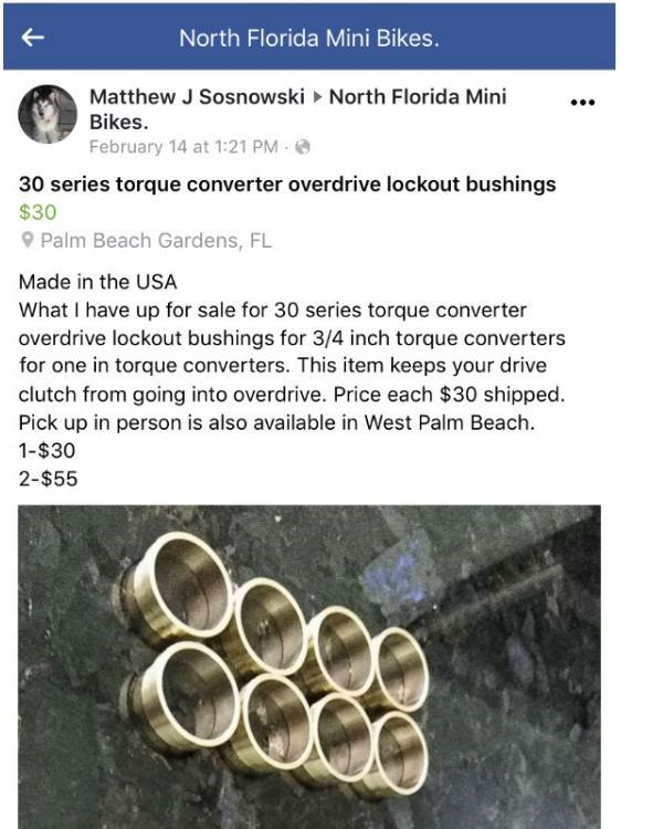
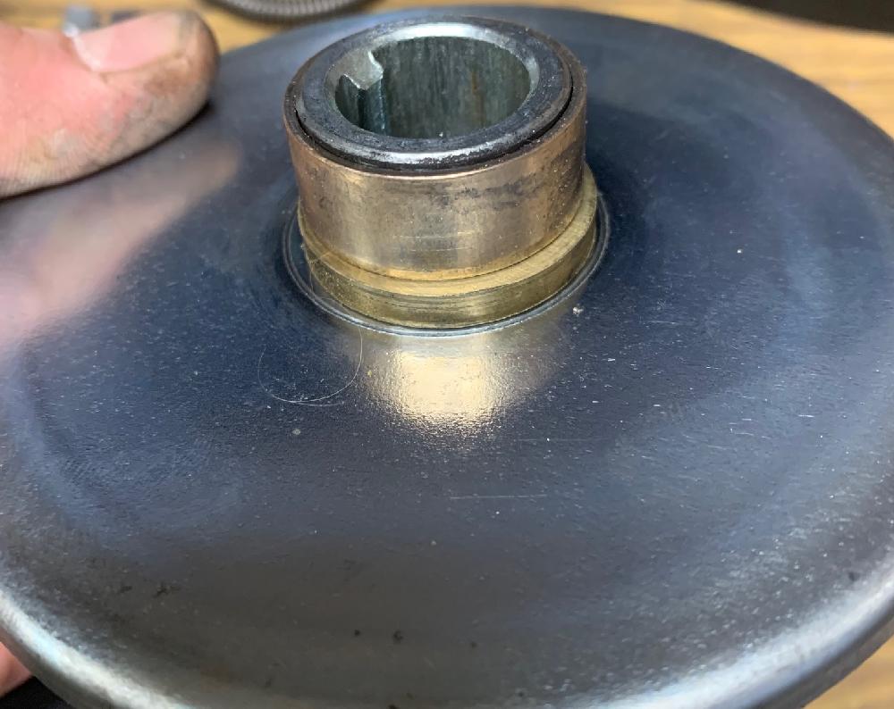
on the main topic: I have read you can get more speed out of the setup by making a spacer that keeps the clutches out of overdrive and I've read a few posts where people claim they've done it. but I haven found a good description or any pictures of what these should look like and where they should go. I could try to figure it out but I don't want to get it wrong and brake something. also the engagement chart mentions mod aluminum driver weights that are even lighter at 90 grams but I cant find a source for those.
If anyone has a set of these pleas post a picture of them and a description of how they work. I'm sure I'm not the only one this will help.