They flicker Paps, as the AC varies from 2-10 VAC, and the sine wave goes from negative to positive to negative, etc. That is why they flicker. The variable voltage due to RPM, really doesn't reach the 12 VDC (presumably) that the bulbs are optimal at. (dimmer)
You need DC from a battery preferably, or rectified AC, as it knocks off the negative voltage, but my still flicker, and will definitely dim the bulbs at low RPM.
So yeah, it will work, in much the same way a wooden block safety wired to the swing arm works to maintain chain tension.")
You need DC from a battery preferably, or rectified AC, as it knocks off the negative voltage, but my still flicker, and will definitely dim the bulbs at low RPM.
So yeah, it will work, in much the same way a wooden block safety wired to the swing arm works to maintain chain tension.
That's what I thought, but I'm not no electronical wizard by any means. I know diodes are kinda of one way valve for electrical current. The reason I was asking, is that I plan to make a lighting coil from scratch and I need to know how to wire it.
Anyway, disregard the above if you want. Member MB165 I'm almost positive did a lot of experimentation with Tecumseh charging systems, or it might have been Ole4. Both of those guys are sharp, so I get them confused on past posts. Sorry guys. They also used a filtering capacitor in it, and were successful in making a "DC" out put.
[MENTION=17758]MB165[/MENTION] [MENTION=3072]ole4[/MENTION] Also Phil68 can build a CMOS chip from scratch, and Jon Pardue has a lot of information on various systems. All of those guys are here somewhere.


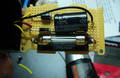
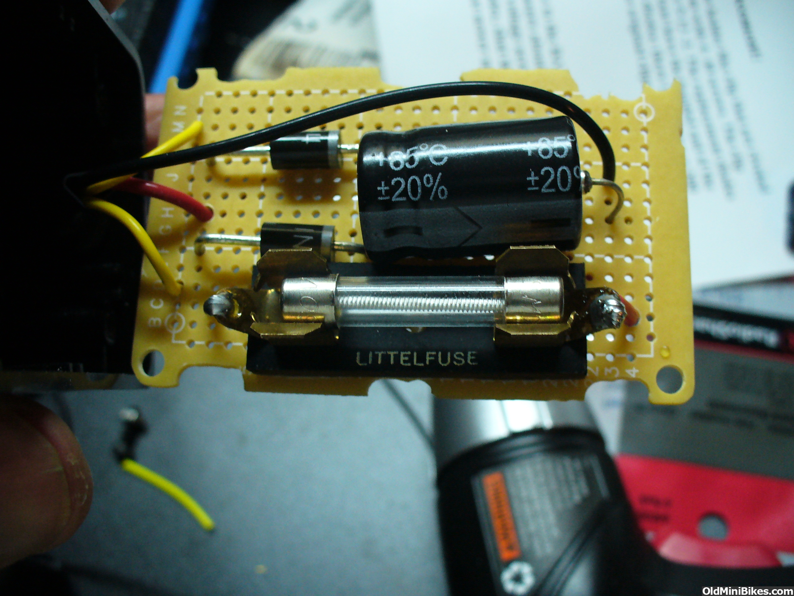
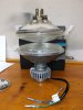
Yes I have and it did not work. I used a 12Vac transformet to test it. It had no output. I then found a wiring diagram for it on a scooter website and it also used chassis ground and a 3 phase alternator. Anyway it is very simple to change a Tecumseh mini bike AC system to DC for led lights I just did it on my rupp fox build project. Problem is my radio shack just closed so no more local access to 1N4007 diodes. Anyway here is a pic of what I used basically a copy of a old tec board with a smoothing cap added inside a little radio shack box
Tecumseh charging coils output "half wave AC" which means one AC leg is "grounded" to the engine block, and the other leg connects to a wire. It will power an electrical load connected across the legs (engine block and wire).
Dual half wave outputs are common. Each leg can power a load. For example, one leg powers a headlight bulb with AC, and the other leg powers a diode rectifier. The rectifier converts AC to DC, for battery charging.
You are right, LED's are diodes... and they run on DC power. You can power LED's from the Tecumseh rectifier. At idle, the LED may pulse on/off as the magnets on the flywheel turn slow. Flickering and on/off ops can be corrected with a capacitor.
You can run dual diodes (Tecumseh did it) into a single DC "bus" that sums the Amps from both outputs. This is enough power to charge a battery and run LED's. Battery = bright at all speeds. With no battery, a capacitor will smooth it.
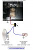
I have 6 Amp diodes on hand that will work. Glad to send a few if you want to run those. This diagram I drew shows the double diodes/DC bus setup powering incandescent bulbs. Easy to replace with LED's.
Jon Pardue
Dual half wave outputs are common. Each leg can power a load. For example, one leg powers a headlight bulb with AC, and the other leg powers a diode rectifier. The rectifier converts AC to DC, for battery charging.
You are right, LED's are diodes... and they run on DC power. You can power LED's from the Tecumseh rectifier. At idle, the LED may pulse on/off as the magnets on the flywheel turn slow. Flickering and on/off ops can be corrected with a capacitor.
You can run dual diodes (Tecumseh did it) into a single DC "bus" that sums the Amps from both outputs. This is enough power to charge a battery and run LED's. Battery = bright at all speeds. With no battery, a capacitor will smooth it.
I have 6 Amp diodes on hand that will work. Glad to send a few if you want to run those. This diagram I drew shows the double diodes/DC bus setup powering incandescent bulbs. Easy to replace with LED's.
Jon Pardue
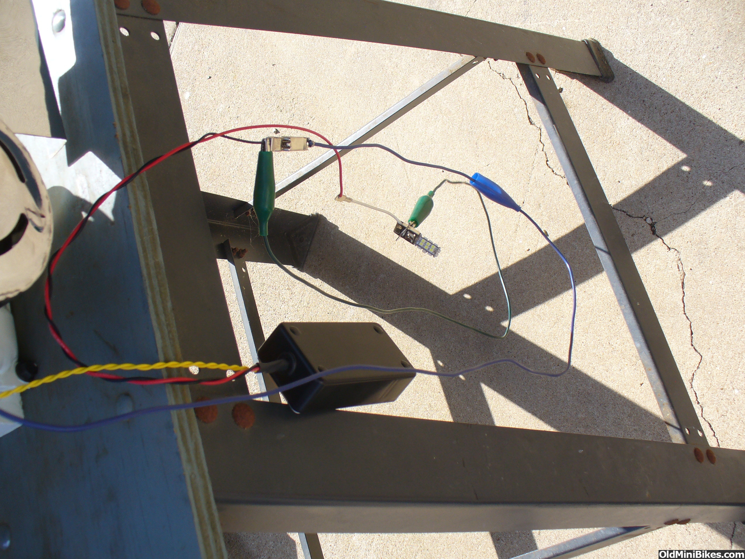
Jon that is the exact picture I saw a while ago (maybe you posted it) that I copied for my setup, I just added a cap to smooth the dc so the led's would not flicker, and it worked great bright as hell even at idle. Keep in mind that both coils are connected and grounded to the chassis which I connected to the negative of my cap.
Ole one of the members here posted the photo of his engine, and I drew the circuit around it. Will add the cap on and put it in here as a reference.
PAP I suggest perusing available and low cost stator windings, PM rotors and regulators for existing engines and bikes. 3 phase is great because there are dozens of 13.8 Volt DC motorcycle setups with regulators already built. Clever machining on right-sized parts might be easier than designing from scratch. Look at a 250cc clone streetbike PMA... amazing regulated output and cheap.
Jon
Well PAP, now that all the dudes I mentioned have checked in, consider the Havasu Dave K.I.S.S. method: Install a LiPo and wire it up. As long as it doesn't burst into flames and burn your jewels and the bike down, (no a worry, unless you recharge while astride) it will provide a few nights of blissful illumination between charges if you use a decent sized battery. (Lap top battery for instance)
Stealing this idea for mine
https://www.oldminibikes.com/forum/...r-top-secret-gilson-build-10.html#post1066765
https://www.oldminibikes.com/forum/...r-top-secret-gilson-build-10.html#post1066765
Its more like a grounded center tap... ends are AC outputs. If you float the ground (hoping to get full wave output) the halves are phase-mismatched... usually reduced output is the result. A rewind or rewire could perhaps solve that.
are probably two magnetic paths so floating the ground is not an option as the
lighting coil operates as two separate generators. in series one generator produces
while the other generator acts as a series inductor reducing the output. sounds
like two diodes and a cap is the only way to go. the problem with LED's is that
they are so fast they will simply blink when the magnet passes the coil. i'd power
a LiPo charger with the dc output and use the LiPo battery as the power source for
the LED.
one other alternative could be to put two LED's in inverse parallel. use a very
low series resistor to lengthen the L/R time constant and you may be able to
get nice long pulses out of the coils. no diodes, no caps!!
:thumbsup:
Last edited:
phil, yes, it does in fact act as two separate alternators, one output for each pole. ( and separate pole for the magneto) we looked into this a few years ago, and figured each pole would need wound opposite direction each other. I tried it lifting the center tap gnd. low output, and it got hot real fast. I still haven't tried rewinding one yet.
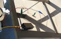
so far im running a 25 w led headlight off one pole, lifted gnd. to a reg./ rec., small battery, and works perfect. rode the rupp in the windber parade last year it looked like a little sun under the lens.
so far im running a 25 w led headlight off one pole, lifted gnd. to a reg./ rec., small battery, and works perfect. rode the rupp in the windber parade last year it looked like a little sun under the lens.
if your headlight is the same as the rupp roadster size you can replace the bulb with a housing which accepts replaceable bulbs. I know a Yamaha grizzly will fit, I used a IT175, I bet a lot other will fit it too. cut of the adjustment boss and glue it in the rupp bezel....that's how I did mine.
Attachments
-
 439.1 KB Views: 59