Rotary Hand Controls

#1
This project is to make a pair of rotary hand controls for the Yellowjacket speedster minibike...another ongoing project also listed in this section.

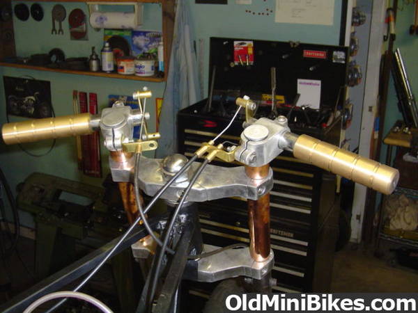
Pic 1- The controls will be similiar to this pair, made for the Ball & Chain bike, but slightly larger, and made from silicon bronze instead of billet aluminum.

Pic 2- Another pair machined in billet aluminum for a friends bike. I tried to talk him out of the spiked grips, but he insisted. I punctured my forehead while assembling the grips to the bike up on the build bench. They may look cool, but they're dangerous. This bike was built for a very young girl to ride.

Pic 3- I originally designed these controls for a custom project to convert a junked old Japanese bike into a cafe racer with as many odd and handmade parts as possible. This is the original sketch I made for the controls while we were sitting around discussing possible parts to make for the build.

Pic 4- This isn't our bike...ours is a Kaw KZ...just a pic to show what can be done with a junker and some skill. This bike was originally a really crappy CB 750, pulled from a pile.

Pic 5- To me, a project isn't interesting if I just grab some new material and throw it in a CNC machine. This project will be done in my garage, with cheap, simple tools, and using as much scrap material as possible. The controls will be made from scrap silicon bronze and brass I pulled off an old wooden sloop in the salvage yard.
 
Last edited:
#3
Continued...

Pic 6- I go looking for bronze propeller shafts because new silicon bronze 1 1/4" round rod is about $63 per foot. There are cheaper types of bronze, but silicon is the strongest, and I use it to turn bushings for a variety of projects, including minibike steering bolt bushings.

Pic 7- The stub end of a previous prop shaft. It cleans up nicely, and I save several hundred dollars by purchasing it from scrap and pulling it myself. That six-footer leaning against the garage wall would be over $300 new for the bronze only...twice that when machined with threads, keyway and a taper to mount a prop.

Pic 8- I also grab alumium or brass tubing from bilge pumps to make other types of grips and footpegs.

Pic 9- This is the mock-up of a proposed fork for the Yellowjacket speedster minibike...made from chopped pocketbike triple tree and rebuilt and lengthened legs from a mountain bike fork. I like it so far, so I'll go ahead and make rotary hand controls to fit onto it to continue the build.

Pic 10- I may end up fabricating a riser/drag bar from scrap later...as I did for the Ball & Chain bike...it depends on the final symmetry of the Yellowjacket frame/fork. I would prefer it to be different from the other bikes I've built. You can see photos on the wall of other SoCal Speedster minibikes posted by minidragbike, and I was already planning the Yellowjacket as I was finishing the Ball & Chain.
 
Last edited:
#4
Fabrication begins...

Pic 1- For minibikes, I start making the rotary controls using clip-ons scavenged from X1 or X2 pocketbikes.

Pic 2- I remove the handlebars from the mounts and use one bar to make two 1/2" pieces and two 2-1/4" pieces. The bar is rough-cut into pieces using a bandsaw, and the pieces are sized and trued on an engine lathe.

Pic 3- The prop shaft I scavenged had the propeller already removed, but still had a steel collar keyed to one end that needed to be taken off.

Pic 4- The collar was hammered off with one of my hundred-year-old hammers. I prefer using tools some people would throw away, and look for them at swaps and fleas.

Pic 5- I used this bandsaw to cut two 7-1/2" long pieces from the bronze. I only use the bender as a stand for the saw...or a boat anchor.
 
#6
Continued...

Pic 6- One of the reasons I designed this type of throttle was because I wanted to make grips from solid material instead of hollow tubing. A normal rotating-sleeve type of throttle dictates the diameter of the grip...but a solid rotating grip body can be made virtually any diameter, and still function.

These are a couple of examples of finial-type gripshafts I make for this hand control design. These look good on really old school-type choppers and bobbers, but aren't really appropriate for the speedster look.

The upper finial was lathe-turned from 1-1/4" brass stock...the same size as the bronze piece above it that will be used for this project. The lower finial was turned from 7/8" brass stock. I think these pieces cost about $12 to make. That chunk of bronze above them is worth about $38...significantly more expensive than brass. Just showing some possibilities...

Pic 7- The two bronze gripshafts after rough-cutting. They were cleaned up using a wire wheel so the lathe chuck would center and hold better.

Pic 8- The ends of the gripshafts need to be turned down to fit inside the pieces cut from the handlebar. 2-3/4" of the end will be turned to a .775" diameter.

Pic 9- The inside diameters of the sleeves cut from the handlebar were cleaned up and measured .780". The bronze gripshaft rotates inside this sleeve.

Pic 10- After cooling, the sleeve was inserted over the gripshaft to ensure it turned smoothly and was sized properly to prevent wobble or sticking.
 
#7
Continued...

Pic 11- A centering drill...used in lathes to find and drill the exact center of the piece. I also use them in CNC mills for engraving. This one is 1/4", and I'm using it to start and countersink a hole in the end of the gripshaft to be tapped for a 1/4" x 20 retaining screw. This screw will later attach the arms for the cables running to the carb, clutch and brakes.

Pic 12- The tailstock, used to drill and cut tapers.

Pic 13- 1/2" drill chuck, mounted to the tailstock on a Morse #2 taper shaft. The graduated scale on the tailstock allows me to run the centering drill in just far enough to start the hole for a regular twist drill to finish, and countersink, or de-burr the drilled hole using the tapered body of the centering drill.

Pic 14- Finishing the 1" deep hole...this is a 13/64" drill used for holes that will be tapped to 1/4" x 20.

Pic 15- Hand-tapping the drilled hole. It is possible to tap using the tailstock...or 'power-tapping' as it's called, but I'll run the risk of breaking the tap off in the $38 chunk of bronze if I'm not careful.
 
#8
Continued...

Pic 16- The gripshaft is now ready to be flipped around in the lathe chuck to turn the handgrip portion. I usually make several heavy paper templates before deciding on the shape of the grip. This is the template that eventually became the spike grip seen in the second pic of this project...the one that I stabbed myself in the forehead with...

I'm going to take a break now, and cut some templates to ponder...

Pic 17- I rough-turned the gripshafts to clean them up, and buffed the mounts after I re-tapped them for heavier stainless steel screws. I made a paper template of Thunder Cycle's Torpedo grip, a shape I thought would be appropriate for the 'speedster' look, but I keep seeing the symmetry of the fork already appearing in the rough-turned shape of the grip. The long cylindrical look of the fork legs is already tied in to the look and shape of the grip as it is now. I may just leave them almost as they appear now.

The springs and ball bearings in the pic are for the centering detents...the next machining step. These hand controls rotate both forward and back, and are spring loaded to return to a center starting point when released.

Pic 18- I use three different compression-rated springs, depending on the bike the controls are being made for...lighter for minibikes, but all are 1/4" diameter. The ball is 1/4" also.

Pic 19- The detent is machined into the grip body, and the length of the spring and ball give me the depth to drill the 1/4" hole. I measure both compressed length and uncompressed, splitting the two readings for the drilled depth because I want the detent to operate midway between these two points.

Pic 20- Using a drill press fitted with a tubing jig, I drill a pilot hole through the sleeve and into the grip body. This hole is half the diameter of the ball, and acts as the sleeve detent. The grip body is inside the sleeve during drilling to prevent a burr being raised on the inside diameter of the sleeve, and to start the next hole to be drilled.
 
Last edited:
#9
Continued...

Pic 21- After removing the sleeve, I use the pilot hole as a guide to enlarge the hole in the grip body to 1/4". The depth stop on the drill press has been set to the midway compression length of the spring and ball combo.

Pic 22- Notice that the hole in the grip body is large enough to insert the spring and ball, but the smaller hole in the sleeve prevents them from coming out of the grip body.

Pic 23- To assemble, the spring is inserted into the hole in the grip body...

Pic 24- The ball is placed on top of the spring...

Pic 25- And using my thumbnail to compress the ball downwards, I slide the sleeve on. The sleeve will be clamped into the mount and be stationary...the gripbody rotates, and this spring and ball detent acts as the center position, midway between rotation.
 
#10
Continued...

Pic 26- It's important to note that the sleeve is not clamped into the mount over the detent area...this would interfere with the operation of the ball moving freely and engaging the detent hole. This is the underside of the rotary control...the detent cannot be seen with the controls mounted on the bike, but is reachable from underneath for lubrication, if necessary.

Pic 27- Because I use a tubing jig to drill the detent holes, I leave the grip body in a rough-turned cylindrical shape until after the detent is machined. Shaping the grip body beforehand may make it more difficult to locate properly in the jig. I later remove the sleeve and detent, and machine the final shape of the grip. For this bike I chose to keep the cylindrical shape because I thought it worked well with the shapes seen in the forks, but I did machine some grooves into the grip after reducing it's diameter to the same diameter as the fork legs. I sometimes put rubber O-rings into the grooves, but they degrade quickly and need frequent replacement. I may knurl the grip later.

Pic 28- A side view...I chose the shape for the grips based on how they would look from the front, but I usually walk around a piece several times, looking at it from all angles.

Pic 29- Rear view...these controls may not need a riser/dragbar combo on this frameset...we'll see.

Cable arms are the next, and possibly last, pieces to be fabricated...
 
#12
Glad you like it...there's some pics of the frame shape for you to decide what kind of seat you want to make for it...I'm sure it'll be something cool.
 
#13
A lot of the narrative is superfluous, but I'm also trying to make it as complete as possible in case anyone else wants to make some of these controls. They look interesting, work well, and are very different from anything else out there.

I didn't copy them from anyone, but I hope someone will alter and improve them, and make some more. I didn't patent the design...everyone please feel free to play around with the concept and try some variations.
 
#14
I am still working on this project...

Pic 1- I made the cable arms...the original sketch shows them screwed and pinned to the gripshaft, but I've been slotting the gripshaft for the last couple years, eliminating the pin.

I started to fab the barrel adjusters and mounting brackets, but stopped after I cut the brackets 1/4" too short, and crushed a lathe-turned brass barrel adjuster while I was threading it. I'll finish them when I stop making mistakes. I'm not sure when that will be...

I could buy most of these pieces, like barrel adjusters, for pennies...
 
#15
The finished controls...


The cables slide loosely through the guides on the arms, pulling against the small stop on the end of the cable, or just sliding, depending upon which direction the grip is rotated.

Spring tension on the cables allows the centering detents to return the grip to a 'neutral' position when released.
 
Top