Bride of Frankenstein - a cure for leftover parts cluttering the workshop.

Tanshanomi

Well-Known Member
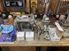
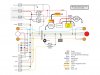
Shortly after purchasing The Bride’s LCT 208 Stormforce engine, I also picked up a 60-watt charging coil and electric-start flywheel. I intended to stick with the stock 27-watt coils initially, and upgrade the alternator output down the line, once I’d ridden the bike. Unfortunately, I dropped an M6 steel washer while fabricating an intake support bracket, and it dropped right down behind the flywheel. I couldn’t locate it anywhere, and I was confident it had stuck to one of the magnets. The flywheel needed to come off. I guess it was time to upgrade the charging system after all.

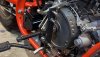
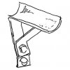
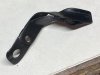
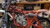
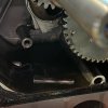
Step one was to whip up a pulling tool. My two-jaw puller was too small to fit, and I’ve never been a fan of “pry-and-pray.” Fortunately, my home-brew pulling rig was just the ticket and the flywheel popped off with a healthy crack.

IMG_5814-HD-1024x576.jpg

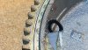
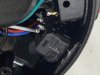
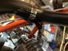
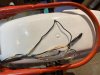
And there was the little bugger, right where I’d expected to find it.

IMG_5815-HD-1024x576.jpg

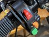
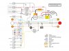
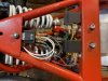
From that point, installation of the new parts was simple.

IMG_5816-HD-1024x576.jpg

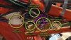
Mo’ magnets, mo’ better.

IMG_5817-HD-1024x576.jpg

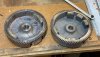
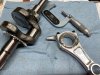
Actually, I don’t understand alternator theory well enough to know if the new flywheel was actually needed, but it’s now a matched set. Sadly, outside of the number of magnets glued to the inside, the two flywheels are virtually identical. No high-RPM shenanigans for this motor! Nobody makes a billet flywheel equipped with charging coil magnets, so this is the best I can do unless I want total-loss lighting and e-start. Which I don’t, obviously.
 

Tanshanomi

Well-Known Member
With the battery mounted to the bike, I’m now working to get all the electrics wired up.

First up was the left-hand handlebar switch, a super-cheapie unit I originally purchased seven or eight years ago for my CL125S resto-mod. The housing broke the first time I tightened the setscrew, so it got thrown in a drawer until I started on this bike. A little JB-Weld inside the housing fixed the original issue, so I thought I was good to go.

IMG_5835-1024x768.jpg

In keeping with its generic Chinesium construction, the switch’s wiring is downright wispy thin. Fortunately, an EE taught me a little trick: tin the wire, fold it back on itself, then tin it again. Then, solder it into the terminal fitting before you crimp it. That technique, along with a more-than-decent ratcheting crimper tool that a friend had recommended, allowed me terminate the skinny wires with suitably robust terminal connections.

IMG_5833-1024x768.jpg

So far so good. But once I’d wired up the turn signals, the left side worked, but the right side was dead. I immediately suspected my wiring, but methodical troubleshooting quickly isolated the issue to the switch assembly. Surprise, surprise. Well, maybe I could repair it? I removed the switch assembly (forcing me to cut off the hand grip first), and carefully opened it up — a process complicated by my earlier application of JB-Weld.

IMG_5836-1024x768.jpg

...And? Negative, Ghost Rider. A circuit tester confirmed that the problem is a defect inside the switch mechanism itself. The flimsy unit was no longer worth any more time and effort. It went into the trash bin and another switch is on its way from Amazon. This one has an alloy housing, and I hope it will be somewhat better constructed.
 
Last edited:

Tanshanomi

Well-Known Member
The extremely long intake runner needed some sort of support, so that the welds at the head flange were not supporting the entire weight of the carb and air cleaner at the other end. In addition, letting it hang off the engine creates a very large lever, amplifying vibrations the carb would experience. And GX clone engines are very buzzy.

So I came up with the idea for a support bracket that would mount to the top of the engine and clamp around the intake pipe. There are two unused bosses in the crankcase — an M8 and an M6 on different planes. I can only bend up to 18 ga steel in my tiny brake; I figured that was a bit skimpy to do a single bent bracket. I’d need to triangulate the bracket for strength. My concept looked like this:

IMG_5844-384x384.jpg

When I got all done fitting, bending, cutting, banging, filing, gouging, welding and grinding, this is how the real version looked:

IMG_5860-HD-1024x768.jpg

Wow, that’s ugly. But despite being crude, convoluted, and amateurish, it fits well and its strength is more than adequate.

IMG_5861-HD-1024x768.jpg

You’ll notice how scratched up the satin black is on the intake pipe in this picture. “Paint-and-primer-in-one” my ass, Krylon. I stripped and repainted it. “Stripped” is probably overstating it; the paint literally wiped off with an acetone-soaked rag, despite being painted weeks ago. I re-did it with Eastwood’s Brake Gray, which is an admirably tough and attractive finish.
 
Last edited:

Tanshanomi

Well-Known Member
I’m still slogging through wiring up The Bride’s electrical equipment. I know a lot of custom bike builders especially dread electrical work, but it’s really not that bad. It’s just time-consuming and requires attention to detail. I’ve previously created wiring harnesses from scratch, and my number-one rule is to start with a complete, totally accurate, plainly readable wiring diagram. This time, lulled into complacency by the engine’s simple ignition system, I disregarded that rule and started out with just a partial diagram. That smart move cost me a smoked turn signal flasher before I relented, backed up, and sat down to hammer out a comprehensive diagram.

Bride-comprehensive-wiring-diagram-1024x768.jpg

Creating this diagram should force you to think through logic of every circuit, as well as the interrelationships between them. Now, it doesn’t have to be laid out on a computer like this, but a half-assed pencil drawing with haphazardly laid out wire routes and scribbled color names isn’t going to cut it. When you’re wrangling a rat’s nest of wiring and Medusa-headed clusters of terminals, you’ll want something instantly decipherable, concise, and consistent.

My drawing still isn’t totally accurate, since the wire leads from the handlebar switches do not match my functional scheme, but that’s a minor issue. I might update this at some point. Meanwhile, I’m busy figuring out how and where all the various bits and pieces can mount to the frame, along with a lot of methodical crimping and heat-shrinking.

IMG_5864-HD-1024x768.jpg
 

Tanshanomi

Well-Known Member
In wiring up the bike, I realized that I had configured both sides of the high/low headlight circuits to switched power, with nothing running to ground. Here's a revised version for posterity, just in case somebody uses this for inspiration someday.
Bride-comprehensive-wiring-diagram-v4-1024x768.jpg
 

Tanshanomi

Well-Known Member
With a the exception of a couple of tweaks here and there, The Bride’s electrical system is complete. All the lighty-up parts light, the horn beeps, the relays…relay, the starter turns, and the indicators indicate. The only thing still unverified is whether the charging system will replenish the battery’s supply of electrons. Fortunately, the ignition is self-engergizing and totally separate from my spaghetti art. Thus, even should the regulator-rectifier melt the wiring, fry the starter motor, and short out the battery, I won’t be left totally stranded. (Well, in the worst case scenario, the whole bike could be engulfed in flames, so I might have that to look forward to.)

IMG_5949-1024x576.jpg

One of the wiring skills that comes with experience is knowing how long to make wires. I was super nervous about ending up with wires that were too short (with good reason in a couple of instances), so I left a lot of my wires excessively long. Furthermore, I was wiring up and testing one component at a time, so I didn’t always tap into the switched power and ground circuits as efficiently as I might have if I was building the whole harness at once. As a result, my wiring displays the same orderliness of a 1970s Moto Morini. The messy appearance is compounded by the lack of any sort of sleeve or loom over the main bundle of wires. At this point, I want the ability to easily trace, diagnose and replace individual leads if something goes awry.

Some parts came out reasonably clean and crisp…

IMG_5946-1024x768.jpg

…while other parts are reminiscent of a 3-year-old’s crayon scribbles.

IMG_5947-1024x768.jpg

And since the components came from a variety of sources, I had to use a bunch of different connector types. I have a whole box of slicone-sealed AMP weatherproof connectors, but I decided that there’s little likelihood of this bike spending appreciable time in rain, mud, or salty roads.

IMG_5948-1024x576.jpg

Could it the whole system be better executed? Yes. But is it functional? Yes! Will be reliable over time? Probably, given the bike’s expected use.

That’s good enough for me.
 

Tanshanomi

Well-Known Member
I opened up the engine to remove the governor, and found this. The oil dipper has broken off the con rod. This is a brand new engine with about 10 minutes of idle running on it. Nothing looks beat-up or gouged inside. Very odd. Has anyone else seen this happen?

IMG_5965.jpeg
 

DaddyJohn

Well-Known Member
I opened up the engine to remove the governor, and found this. The oil dipper has broken off the con rod. This is a brand new engine with about 10 minutes of idle running on it. Nothing looks beat-up or gouged inside. Very odd. Has anyone else seen this happen?

View attachment 302702
Well, the good news is you can say it needed replaced anyway when you get the billet item. :)
 

Tanshanomi

Well-Known Member
I have a new connecting rod, a couple of different pistons, and a gasket set on order. Because of the LCT 208 engine's odd specs, I had to order a GX clone rod and a flat-top 212 piston to go with it. I wasn't sure if I needed a compression height of .550" or .570", and the .570 piston didn't come with the correct wrist pin (the existing LCT one is larger diameter). So, I simply ordered two pistons. They were cheap enough, after all. However, these parts ended up costing me more than the $99 the entire engine originally cost.

IMG_5978.jpg
 

Tanshanomi

Well-Known Member
Man-oh-man, I’m well and truly into it now. I just keep digging this hole deeper. This is my first time inside a commercial/industrial type engine. It’s very simple, which is good, but I’m unfamiliar with a lot of the engineering. I’m a motorcycle guy, and a lot of this seems more car-like than bike-like.

Once I got it apart, I discovered that the LCT had a dished piston, so I'll be using the Tillotson .550" flat-top. Maybe somebody can tell me how much difference the 20 thou difference makes in an otherwise stock motor. I really don't know.

As a side note, one of the reasons I bought two different pistons is that from the website photo, it didn’t look as though the .570 piston came with a wrist pin. Actually, it did.

IMG_6016-HD.jpg
 

DaddyJohn

Well-Known Member
They’re likely fine, as stock, vs. anything else as stock. It’s just the lack of specific parts support and knowledge-base surrounding modding them (probably stuff you didn’t necessarily know beforehand). I guess you’re forging some knowledge-base for everyone to share though, so I don’t suppose anyone should fault your altruism. :)
 

Tanshanomi

Well-Known Member
IMG_6036-1024.jpg

Well, DaddyJohn's take was spot-on. Attempting to save $60 by buying the LCT engine rather than a Harbor Freight Predator 212 has certainly turned out to be a boondoggle.

I plasti-gauged the big end this morning, only to find that I had less than 0.001″ clearance. To verify the issue, I brought out the micrometer. Sure enough, the LCT crank journal is 1.201″— way too big for a standard clone rod (1.85″ nominal).

I briefly considered buying a new crankshaft, but since both the big end and wrist pin were non-standard diameters, I can’t assume the crank bearings are standard size, either. The second thought that occurred to me was to simply go to Harbor Freight and buy a complete different 212 engine. But the whole idea behind this project was to use up the spare junk sitting around my shop; I certainly don’t need a spare LCT engine cluttering up the place.

So, I’ve decided to simply re-install the stock rod and piston. I can fabricate a sheet metal oil dipper that will fit under the rod bolt heads, similar to the separate slinger old Briggs & Strattons used. Since my charging-coil-equipped flywheel limits my RPMs anyway, the billet rod isn’t really a requirement anyway.

I've got family stuff that will take up the next couple of weeks, so the workshop will have to wait for a while.
 

DaddyJohn

Well-Known Member
It’s inspiring to packrats everywhere that you’ve used spare parts and otherwise less-than-useful items to get where you’re at with the project; it’s come out great so far. So much so, that I wouldn’t fault you for substituting something better here and there at modest expense to end up with a substantially better result. I think it does the work done to get to the finish line more justice.
 

Tanshanomi

Well-Known Member
I didn't buy another engine, but @DaddyJohn did convince me to "substitute something better" than the stock crank, rather than go back to stock engine innards. I ordered a GX clone crank from 0MB Warehouse for about $50 including crank shims (that I won't need). Not only will I now be able to use the ARC billet rod and Tillotson flat-top piston, but I won’t have to spend extra shop time fabricating the bolt-on replacement oil dipper I planned to make.

After too many weeks without making progress, I was able to get into the shop this morning and check out my new crank. The Plastigauge now reads between .002″ and .003″ — right in the sweet spot — and I verified that the crank mains fit the crank bearings in the cases. I’m now eager to find a few hours to get the engine assembled.

IMG_6105.jpg
 
Last edited:
Top