Dr. Shop Teacher's JFF Gilson Knight Rider
- Thread starter Dr. Shop Teacher
- Start date

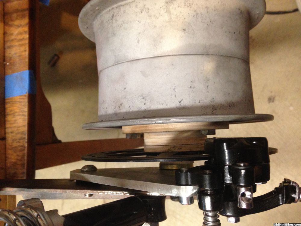
Had a few minutes before heading north again, so I checked the rear hub for proper dimensions. My eyeball said the front and rear would be the same, but "nope." The spacer to the disc on the rear is 1/4" narrower, so two different hubs will need to be machined.
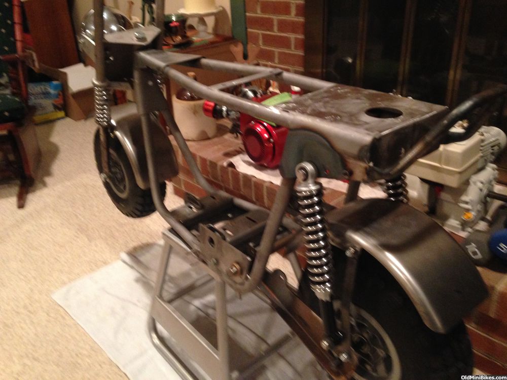
I also wanted to see if I could flip the caliper forward of the shock, and that is also a "nope" without hacking the h-e-double toothpicks out of the swing arm. A note about the swing arm: It's an Allis swing arm, which I think is longer than the Wards swing arm. The shocks seem to be raked a bit more than on the Wards-derivative bikes. Pics are wacky again.
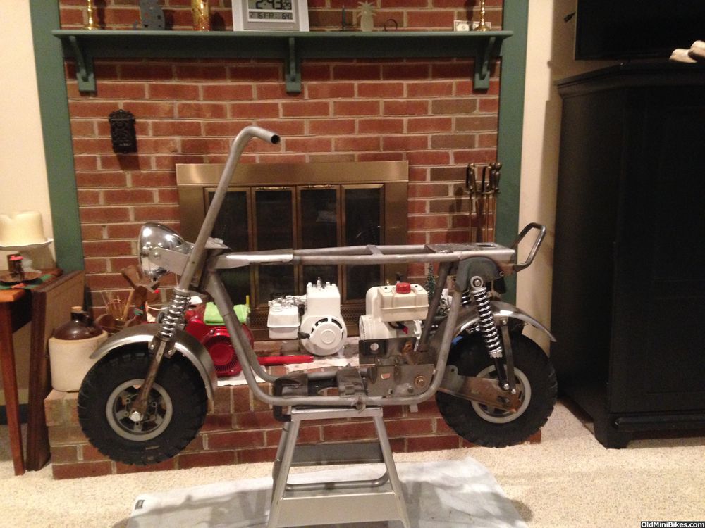
Shocks mounted (I'm using stainless for all hardware).
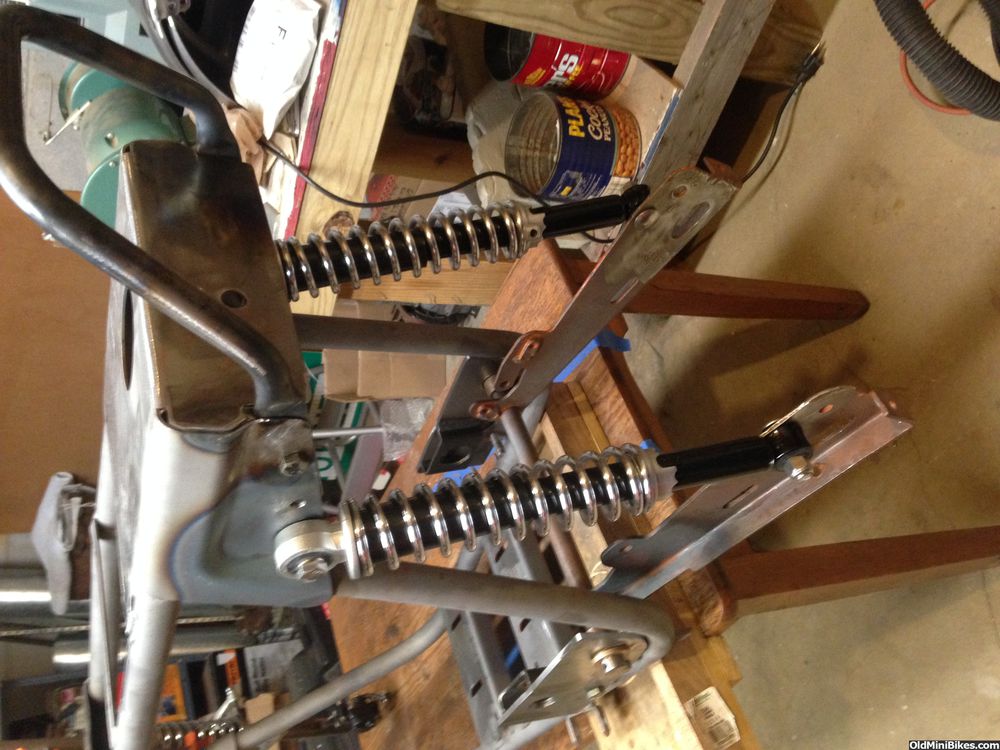
Side view:
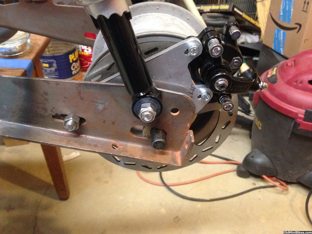
Another view:
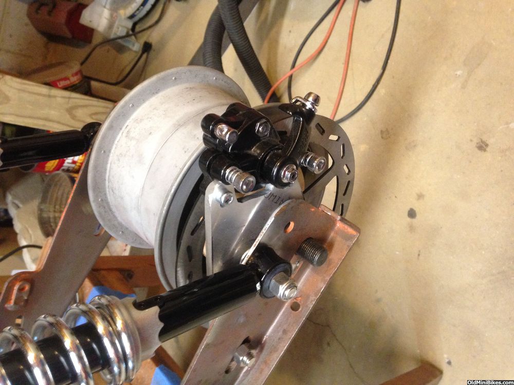
From the rear (note that I had to step off to clear the shock carriage bolt):
I also wanted to see if I could flip the caliper forward of the shock, and that is also a "nope" without hacking the h-e-double toothpicks out of the swing arm. A note about the swing arm: It's an Allis swing arm, which I think is longer than the Wards swing arm. The shocks seem to be raked a bit more than on the Wards-derivative bikes. Pics are wacky again.
Shocks mounted (I'm using stainless for all hardware).
Side view:
Another view:
From the rear (note that I had to step off to clear the shock carriage bolt):
Playing a little bit....with brazing.
I had read that a MAP(P) torch would get metal hot enough to braze. So, I figured I might as well try it. Given that I haven't done any welding or brazing in 26 years, this might prove to be a challenge. I wanted to fill the gas line holes in the shroud in the hopes I'm able to powder coat it to match the bike (gotta keep up with [MENTION=47323]OND[/MENTION] :laugh: ). I made up a simple patch that I brazed inside the shroud and then used brazing rod to fill the hole. Took a long time to get the two pieces of metal hot enough for the rod to flow, but it did. An angle grinder and a pad sander cleaned it up.
I stripped the shroud yesterday and removed much of the surface rust inside.
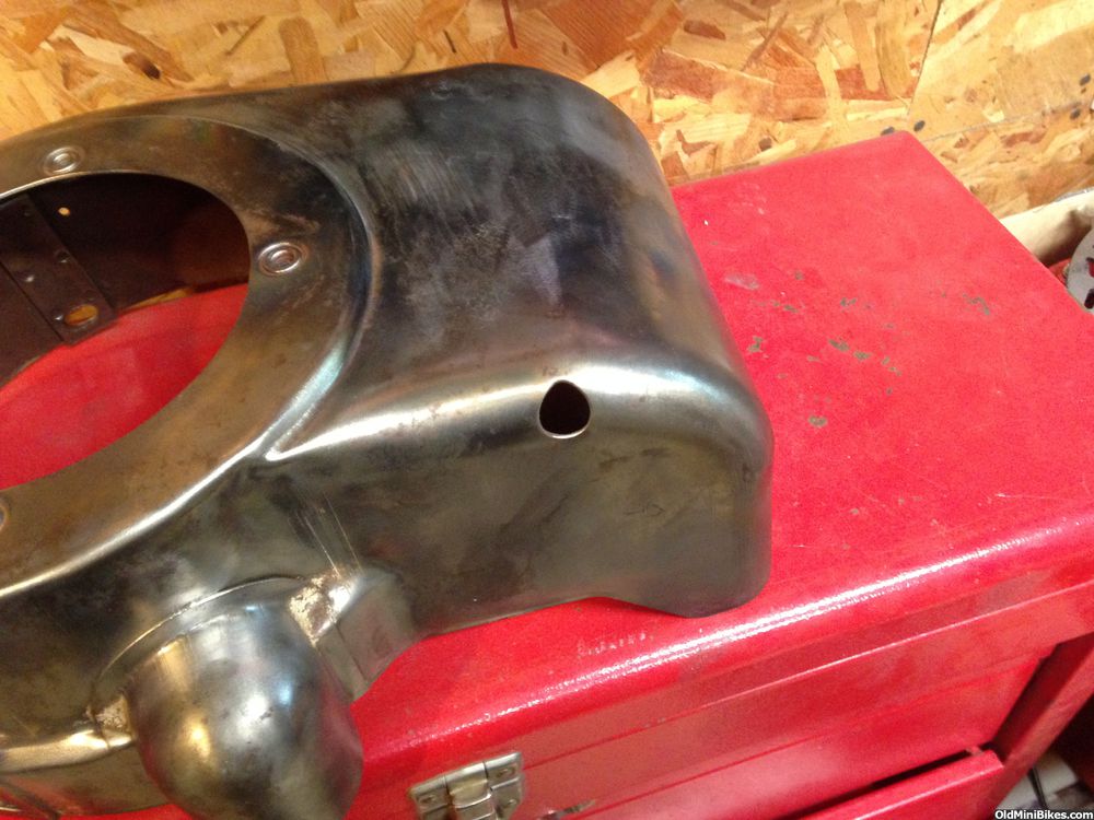
Here's the little patch I made out of scrap.
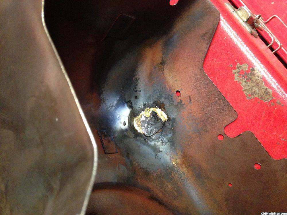
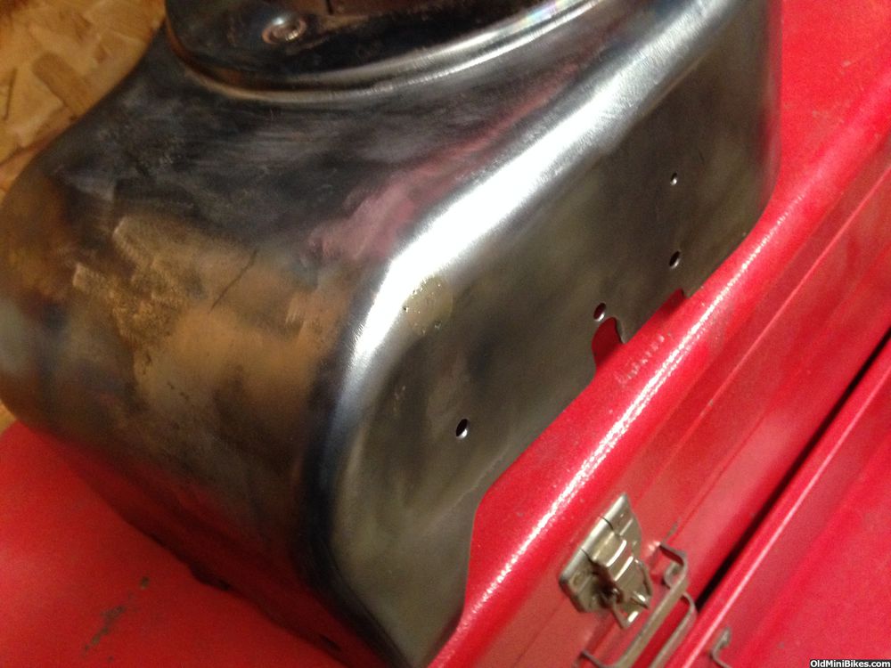
Here's one side done. Another tomorrow while I'm waiting for parts to arrive.
I had read that a MAP(P) torch would get metal hot enough to braze. So, I figured I might as well try it. Given that I haven't done any welding or brazing in 26 years, this might prove to be a challenge. I wanted to fill the gas line holes in the shroud in the hopes I'm able to powder coat it to match the bike (gotta keep up with [MENTION=47323]OND[/MENTION] :laugh: ). I made up a simple patch that I brazed inside the shroud and then used brazing rod to fill the hole. Took a long time to get the two pieces of metal hot enough for the rod to flow, but it did. An angle grinder and a pad sander cleaned it up.
I stripped the shroud yesterday and removed much of the surface rust inside.
Here's the little patch I made out of scrap.
Here's one side done. Another tomorrow while I'm waiting for parts to arrive.
As OwenD says....I didn't either
Here's the other side done. This time, I cut a tear drop out of 22g sheet metal and fit it to the fuel line opening. Heated much more evenly and the braze flowed quickly.
Kinda slobbered on below :doah:
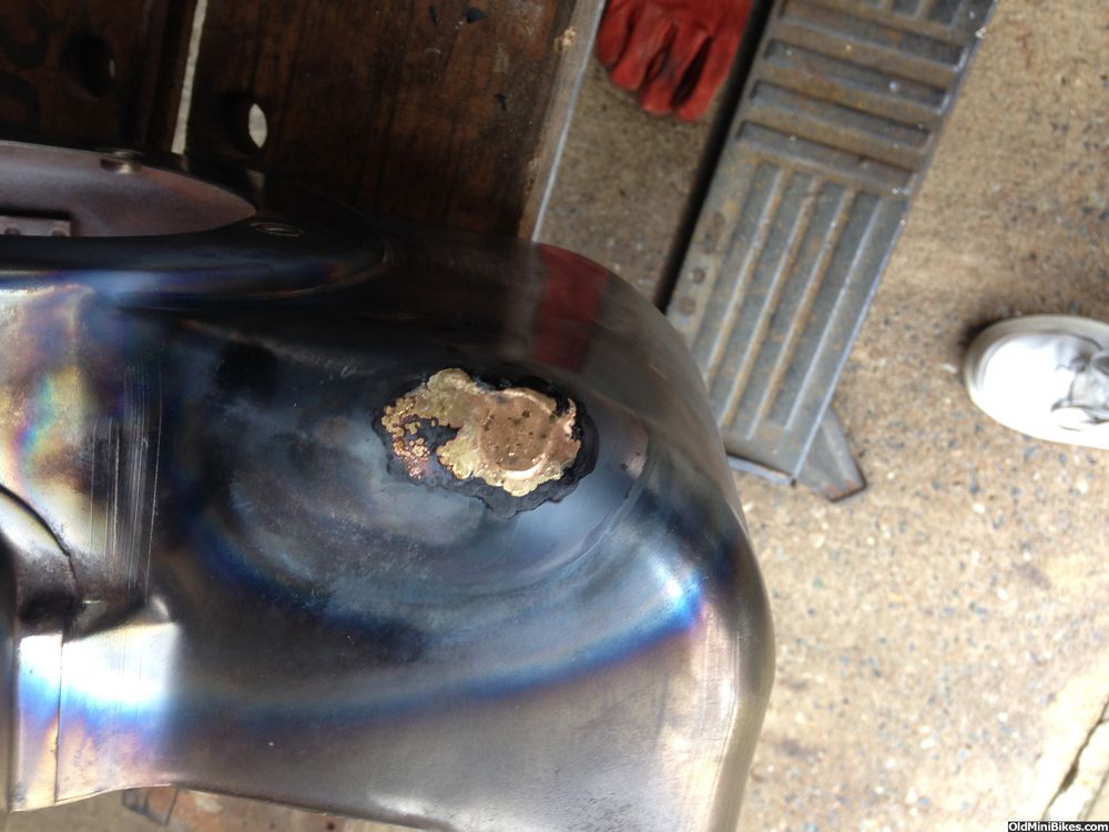
A little grinding--:grind:
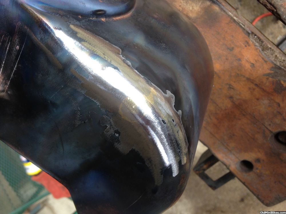
And some sanding....much better.
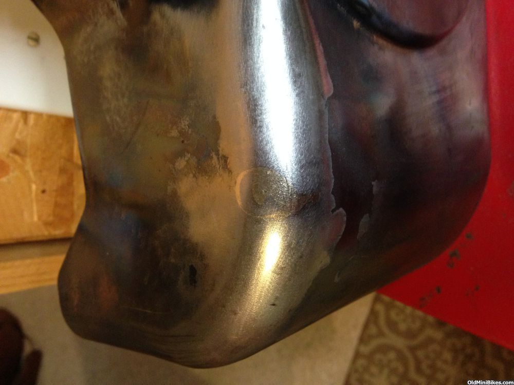
I would have never have thought that would work:thumbsup:
Kinda slobbered on below :doah:
A little grinding--:grind:
And some sanding....much better.
Beginning to look like something...
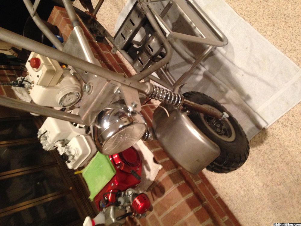
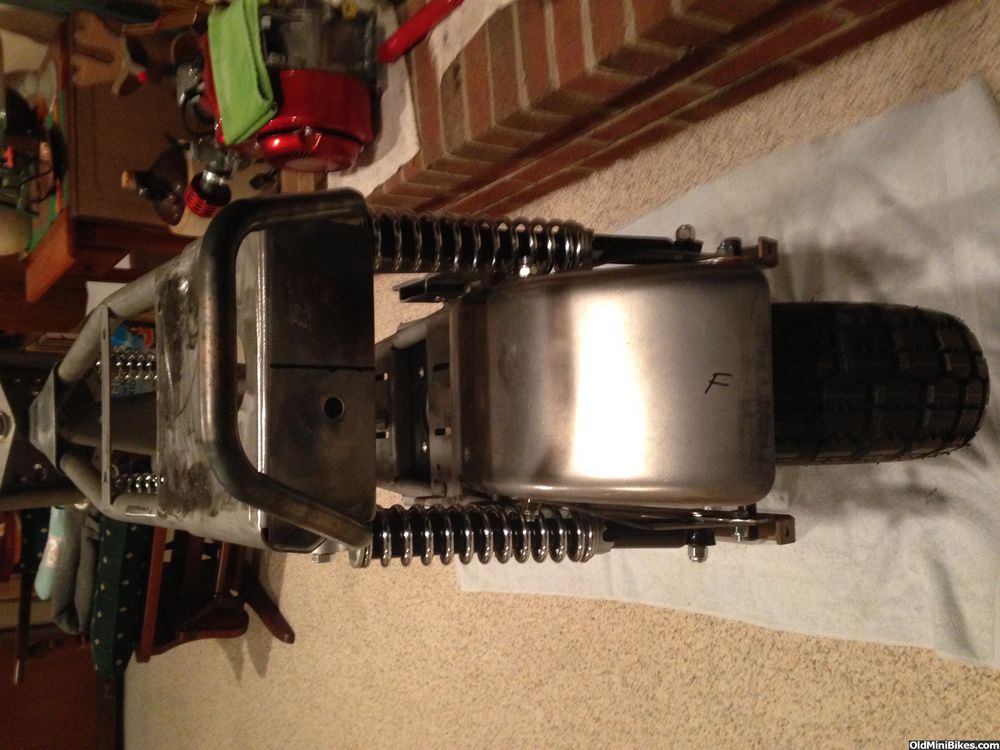
Spent most of the day test fitting and making adjustments. Still more to go, but was able to mock most of the bike together. OldMiniBikes delivered the 5.30-6 tires today, just in time!
Here's a front view (wacky pics again):
From the rear:
At an angle:
Profile 1:
With the monthly coffee cup and the awesome [MENTION=18286]manchester1[/MENTION] seat--
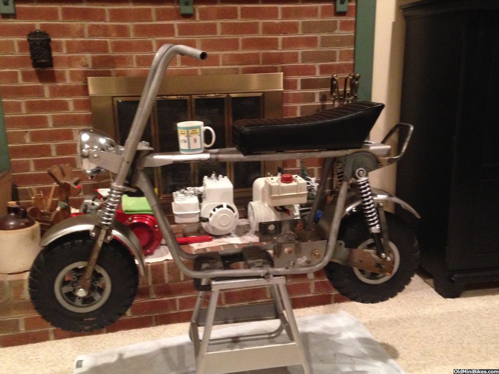
Here's a front view (wacky pics again):
From the rear:
At an angle:
Profile 1:
With the monthly coffee cup and the awesome [MENTION=18286]manchester1[/MENTION] seat--
Battery Box Mount
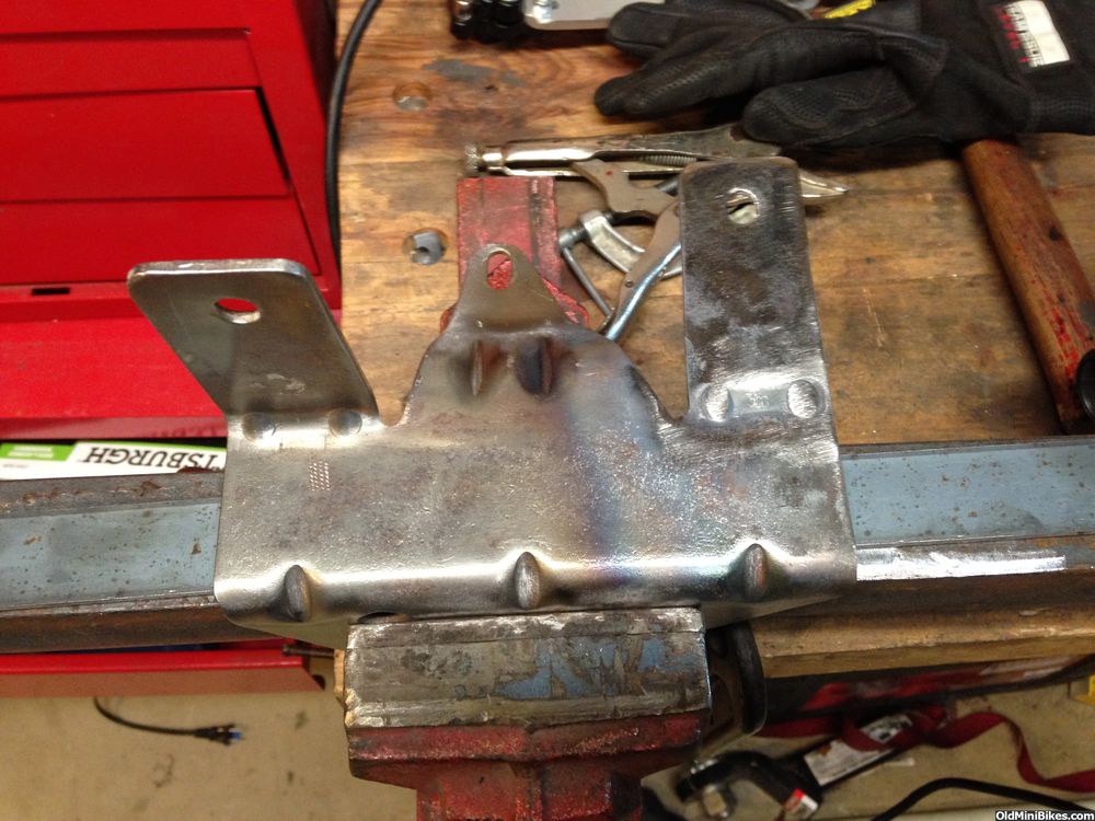
I'm using a fuel tank bracket to position the Lithium Ion battery. The battery is really small but will have well over 200 cold cranking amps. The battery box is actually smaller than the starter motor (from an H-70). First up was flattening the tank tabs to resize them:
Original
Right tab flattened
Then mounted on the engine to locate the position for the new tabs. This required the engine being on the bike and checking clearances to the top rail and the starter solenoid (which will be mounted on the underside of the expanded control plate). The top of the battery will sit roughly 1/2" below the boot height of the spark plug.
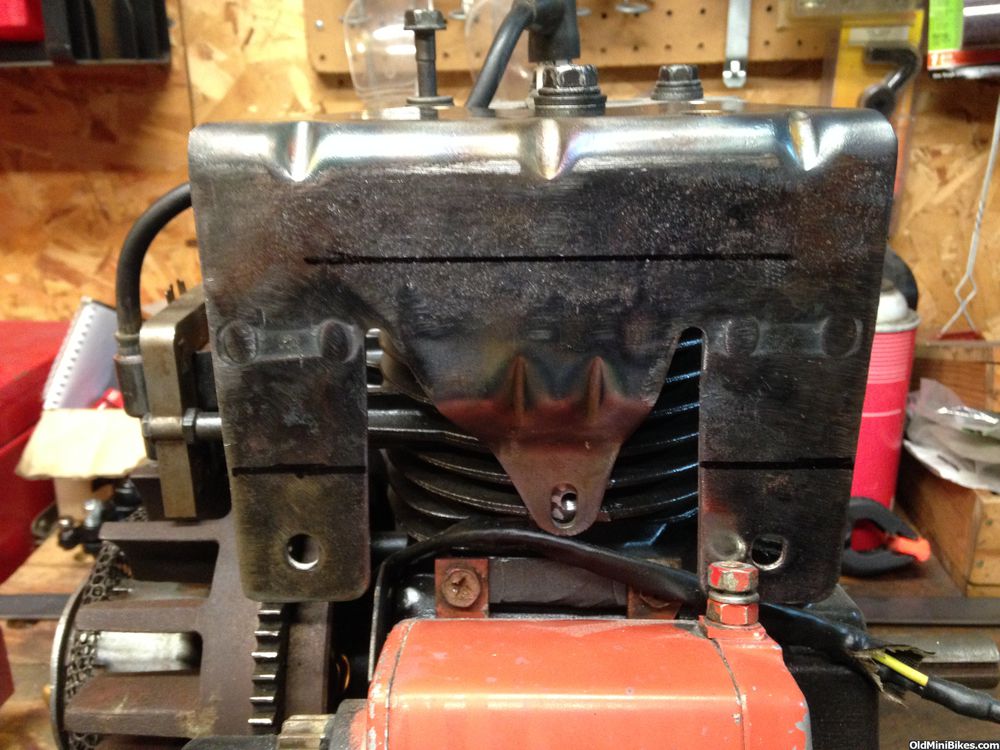
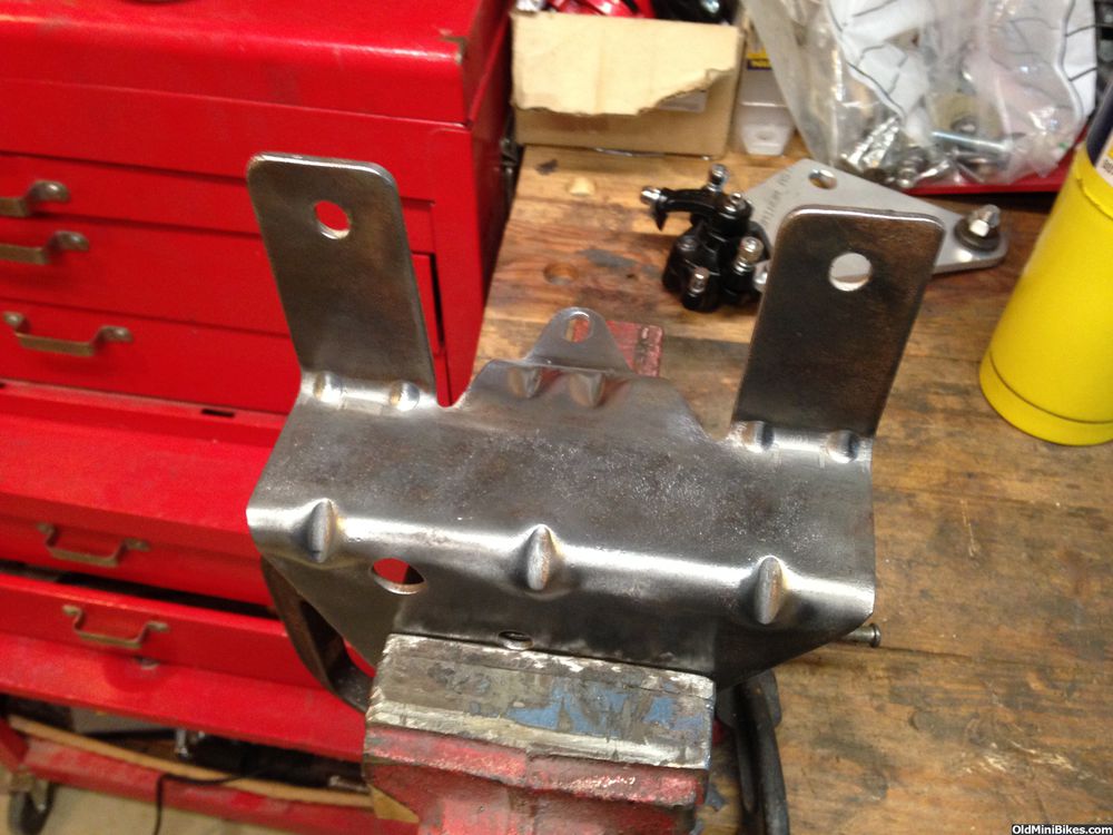
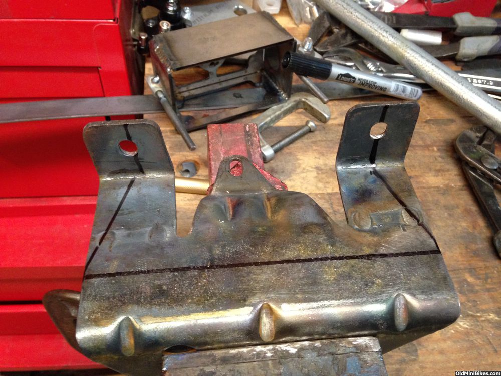
Once the bottom of the box was located, new tabs were shaped (a lot of heat required to do this with my undersized vise).
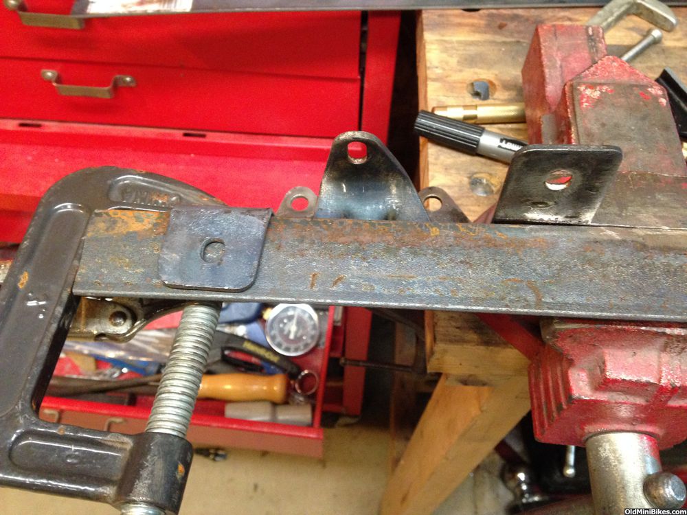
Alignment of the battery box.
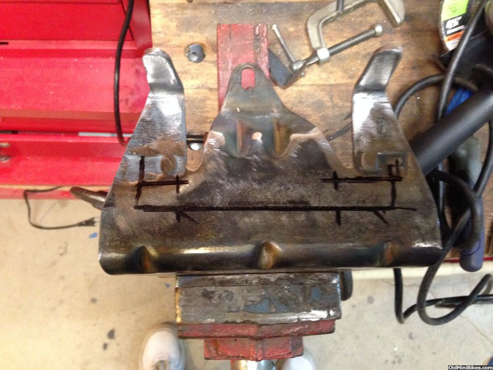
Marking for cutting down to size (bracket is offset on the engine to clear the shroud, so angles are different).
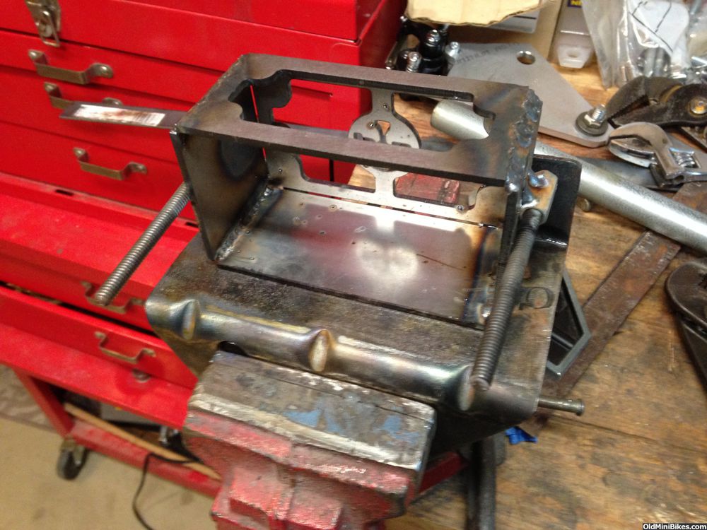
A little action with the sawzall and the angle grinder, poof, one battery bracket.
Here's the box mounted on the engine (another wacky pic). I temporarily used 8-32 screws to hold the box to the bracket.
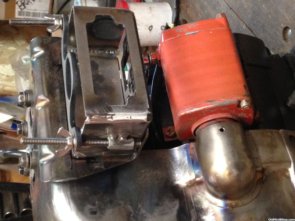
Throttle control is next up, then waiting for parts again!
I'm using a fuel tank bracket to position the Lithium Ion battery. The battery is really small but will have well over 200 cold cranking amps. The battery box is actually smaller than the starter motor (from an H-70). First up was flattening the tank tabs to resize them:
Original
Right tab flattened
Then mounted on the engine to locate the position for the new tabs. This required the engine being on the bike and checking clearances to the top rail and the starter solenoid (which will be mounted on the underside of the expanded control plate). The top of the battery will sit roughly 1/2" below the boot height of the spark plug.
Once the bottom of the box was located, new tabs were shaped (a lot of heat required to do this with my undersized vise).
Alignment of the battery box.
Marking for cutting down to size (bracket is offset on the engine to clear the shroud, so angles are different).
A little action with the sawzall and the angle grinder, poof, one battery bracket.
Here's the box mounted on the engine (another wacky pic). I temporarily used 8-32 screws to hold the box to the bracket.
Throttle control is next up, then waiting for parts again!
Variable Speed Throttle Control (almost from scratch)
Spent time working on modifying a fixed speed throttle control from OldMiniBikes. This engine is a newer engine with solid state ignition and the governor linkage is very different than the points ignition engines. To make this assembly, I needed to take the assembly apart and rework a couple of pieces and add a bracket for the throttle cable.
Here's an old one as an example of what I started with (it's killing me that these photos go sideways--not this way in Tapatalk):
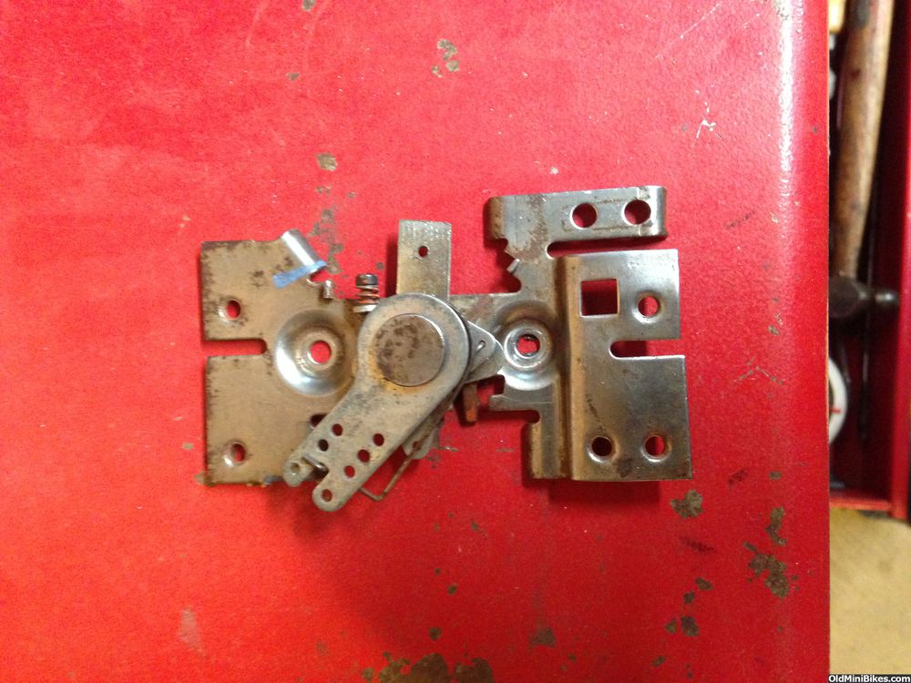
I heavily modified the throttle lever to accept the cable and stop--to bend it, you really need to heat it red hot. You can see the bracket I made for the cable sheath.
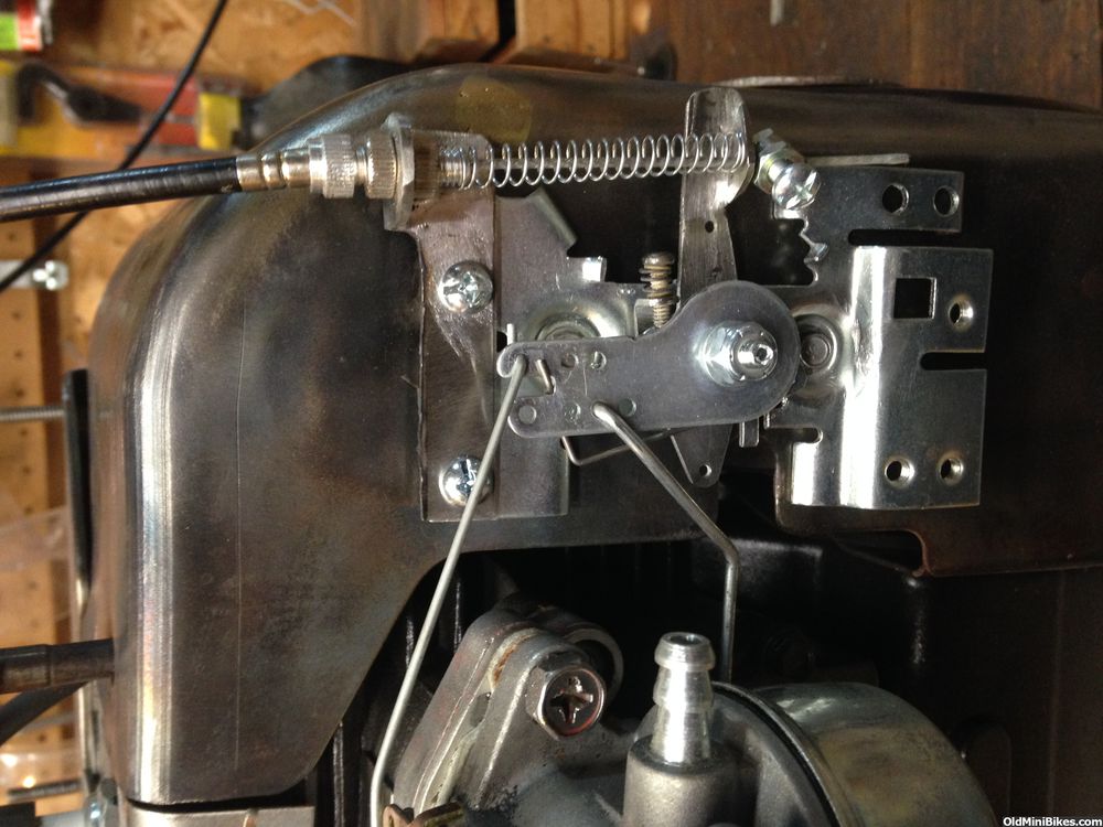
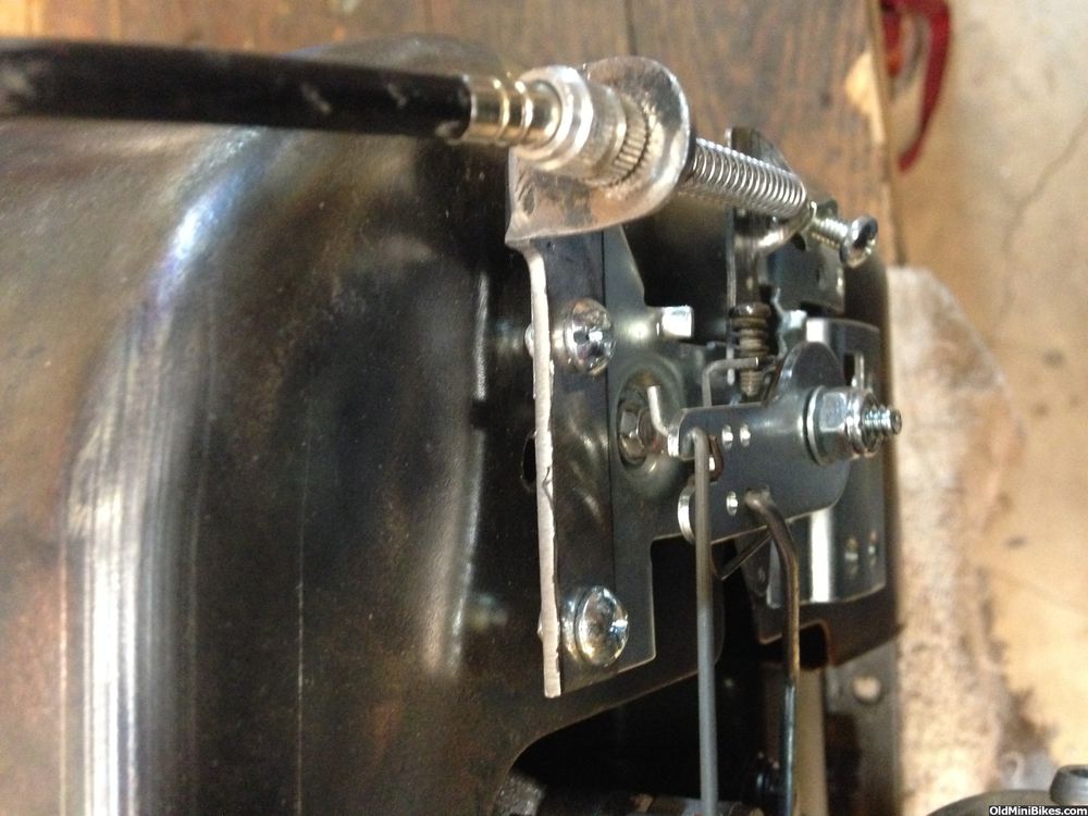
I used 10g sheet metal to make the bracket, and it needed to be heated to bend cleanly. An 8-32 screw and nylock nut hold it all together. A look down:
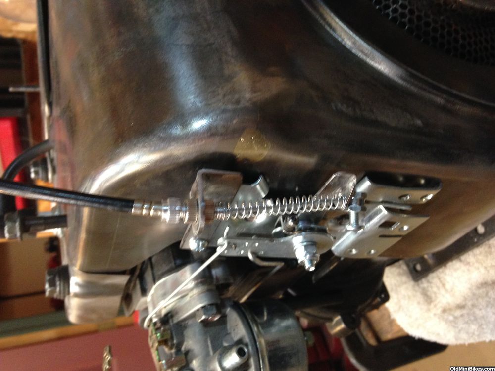
I prefer this cleaner look with the spring on the cable. The spring does a nice job of returning to idle, but I do need to source a slightly longer one at True Value:
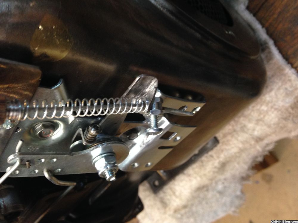
How the cable stop fits. I can trim off a lot of the bottom of the control as it's not necessary.
Spent time working on modifying a fixed speed throttle control from OldMiniBikes. This engine is a newer engine with solid state ignition and the governor linkage is very different than the points ignition engines. To make this assembly, I needed to take the assembly apart and rework a couple of pieces and add a bracket for the throttle cable.
Here's an old one as an example of what I started with (it's killing me that these photos go sideways--not this way in Tapatalk):
I heavily modified the throttle lever to accept the cable and stop--to bend it, you really need to heat it red hot. You can see the bracket I made for the cable sheath.
I used 10g sheet metal to make the bracket, and it needed to be heated to bend cleanly. An 8-32 screw and nylock nut hold it all together. A look down:
I prefer this cleaner look with the spring on the cable. The spring does a nice job of returning to idle, but I do need to source a slightly longer one at True Value:
How the cable stop fits. I can trim off a lot of the bottom of the control as it's not necessary.