Piddlin' Away....Electric
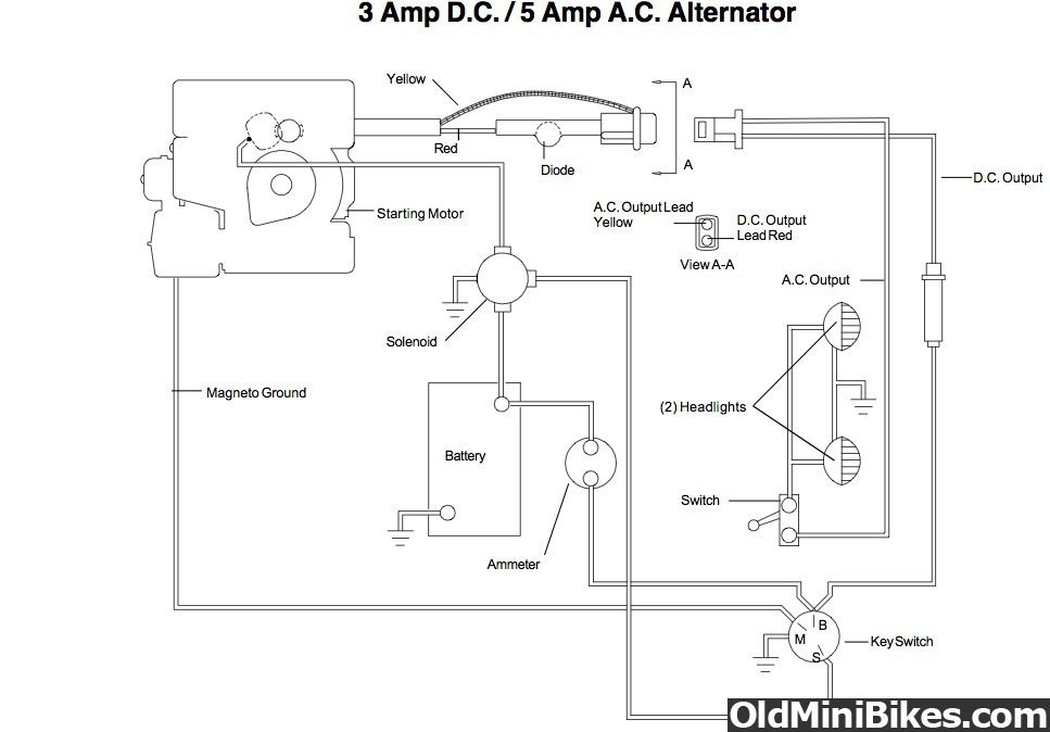
Was waiting for the big parts to come in, so I started on the wiring for starting and lighting. Because the bike will be powdercoated, I need to locate as much as I can close to the engine or on the engine to ensure I have good grounds. The solenoid is an ugly looking part, so I needed to hide it as best as I can.
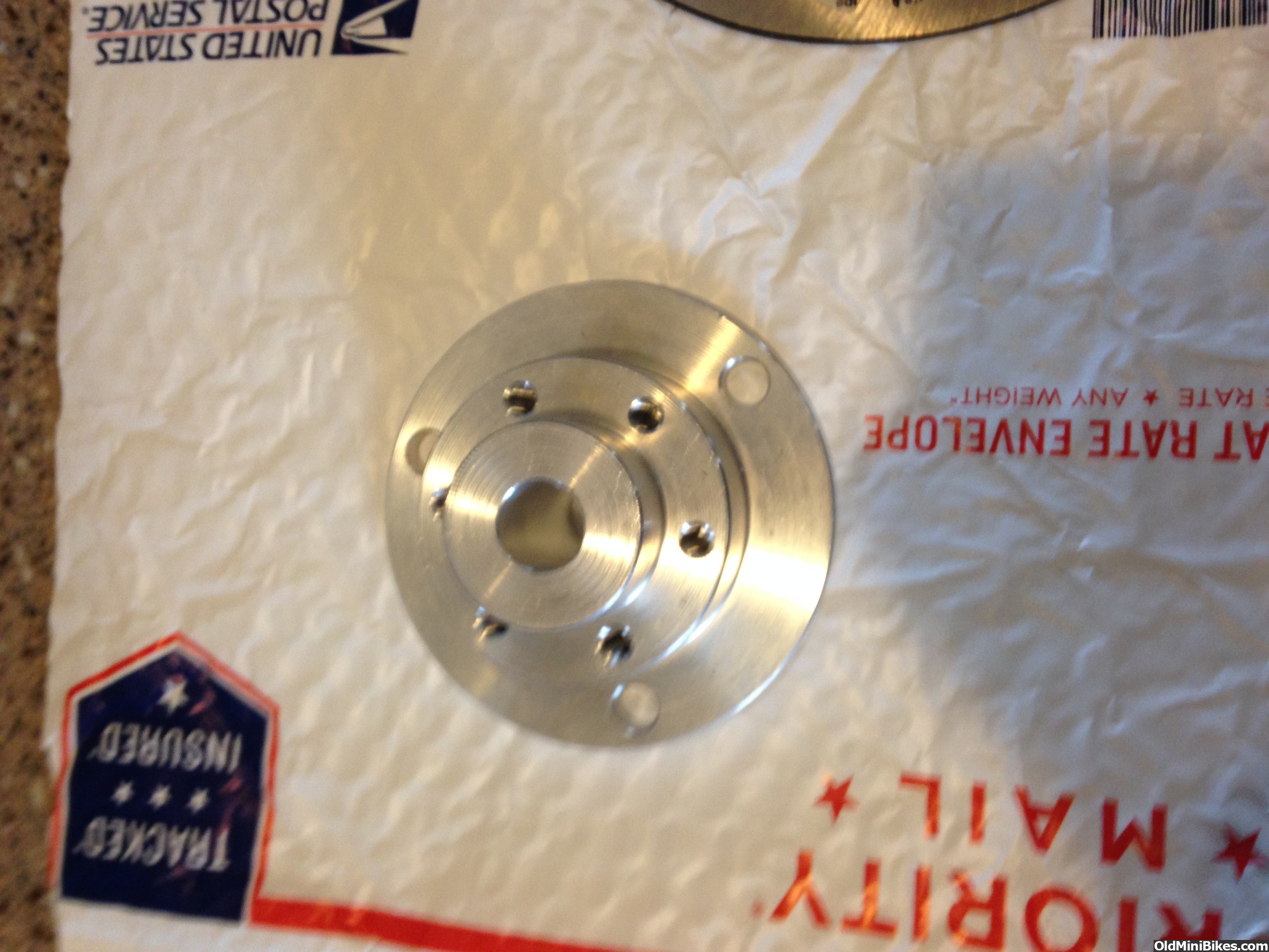
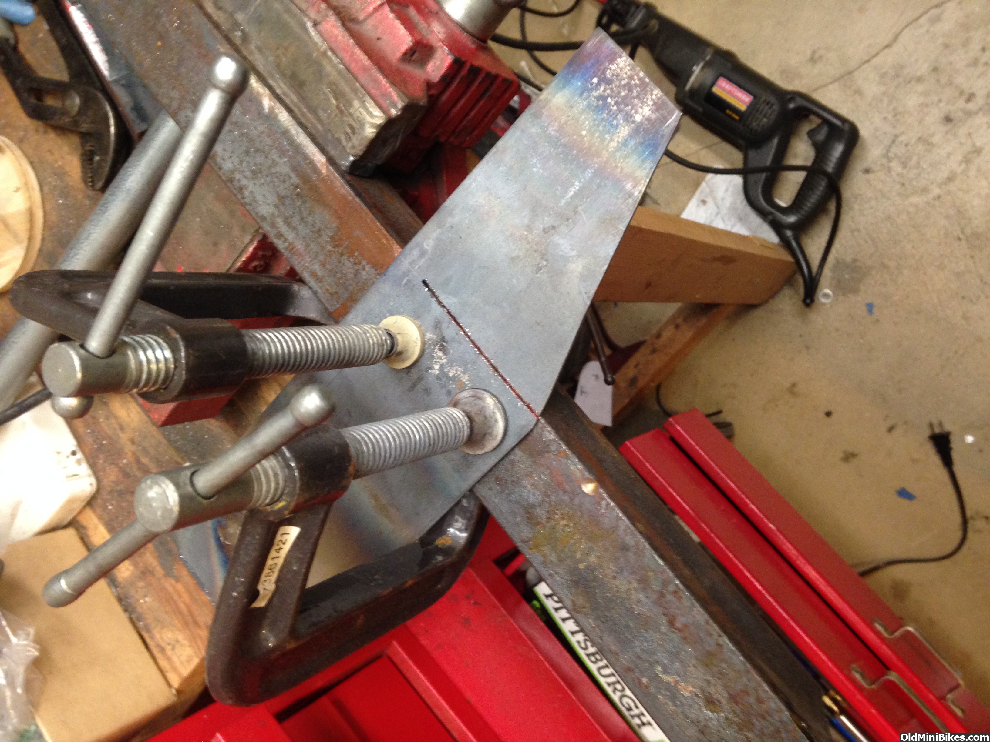
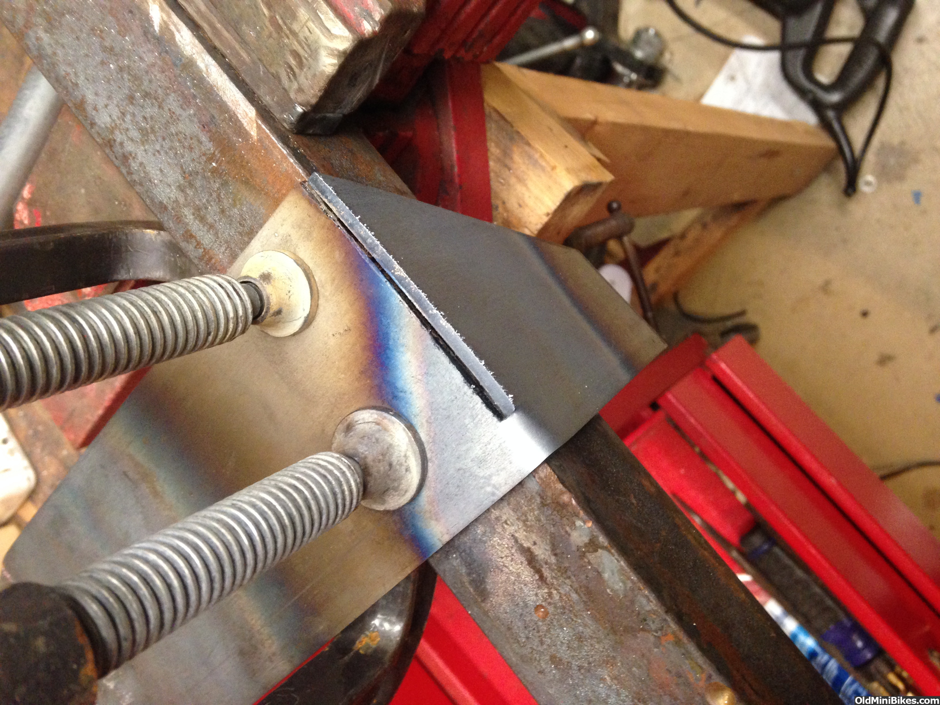
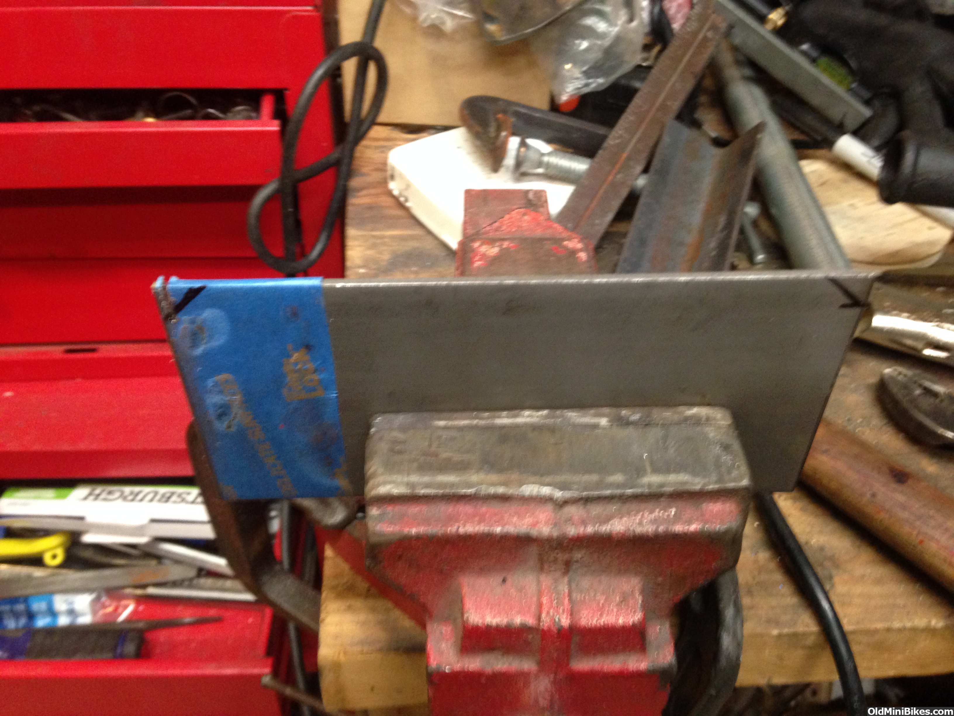
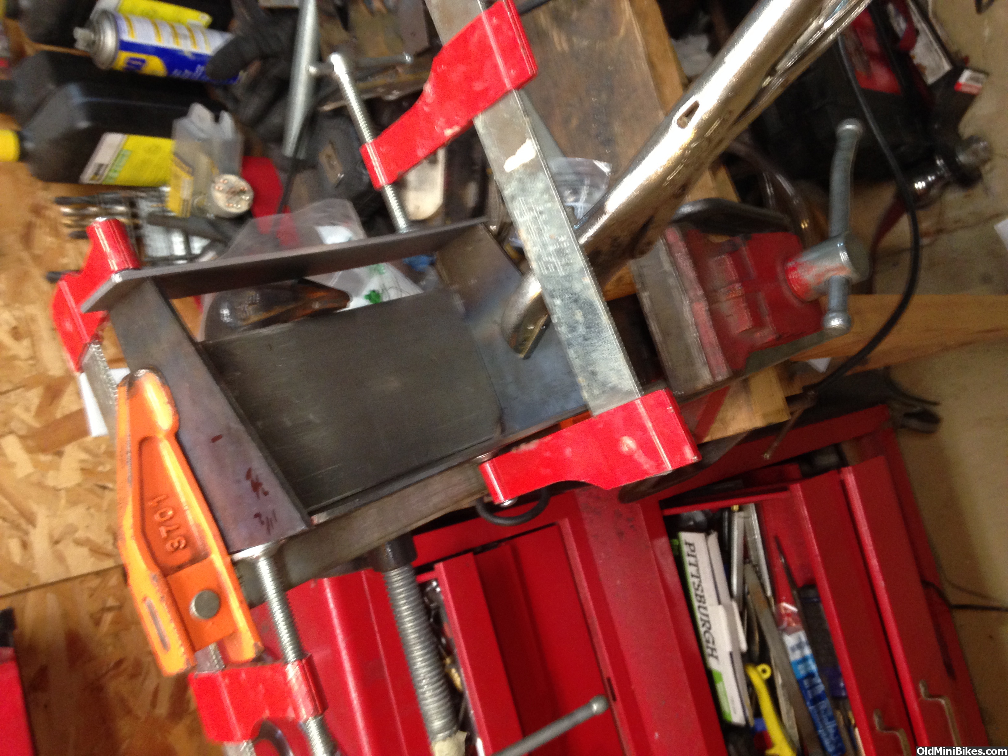
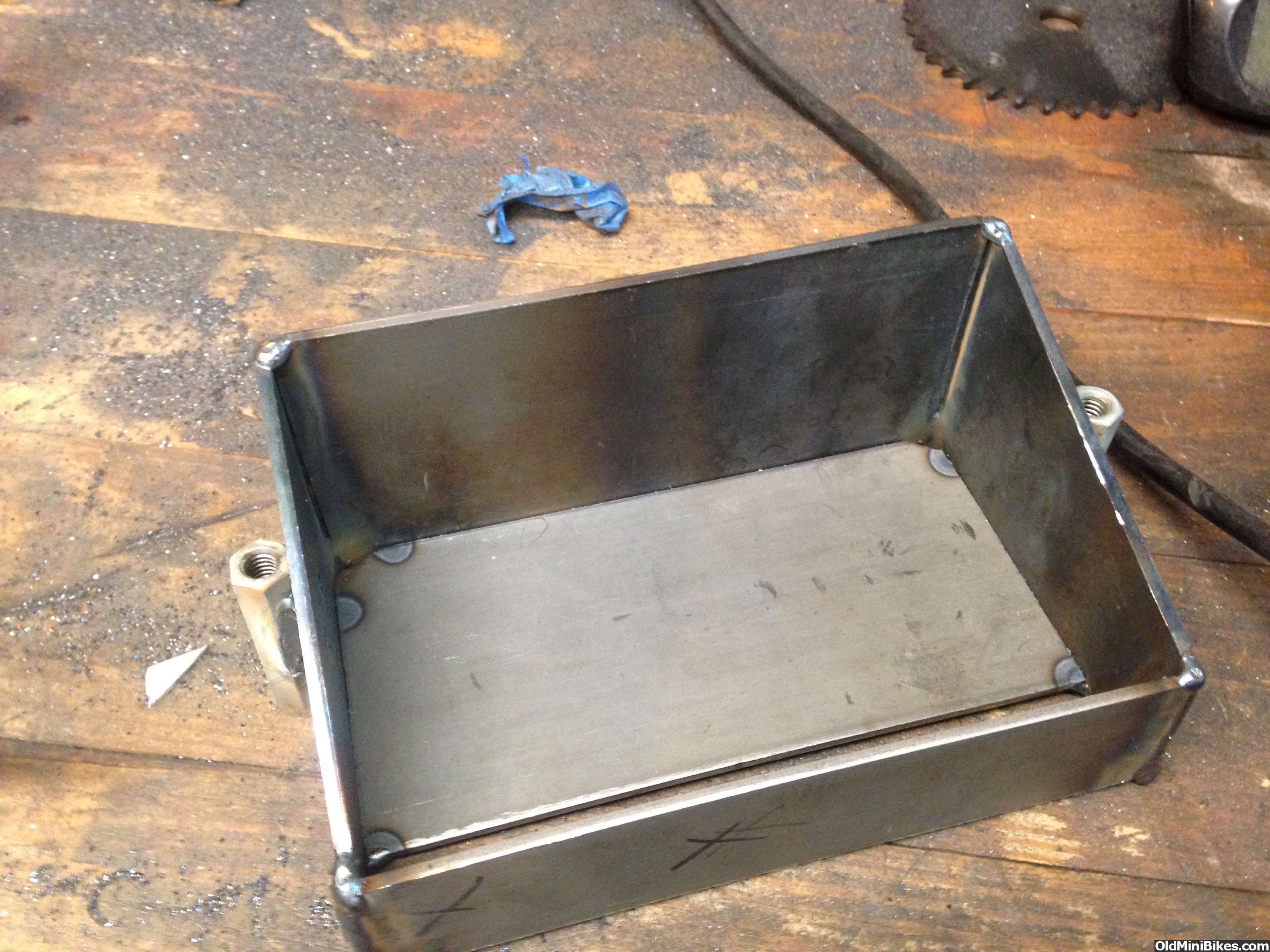
I made a mounting plate that fits to the engine bottom plate. It's an odd looking shape, but that's because the bottom plate has some stampings I had to work around.
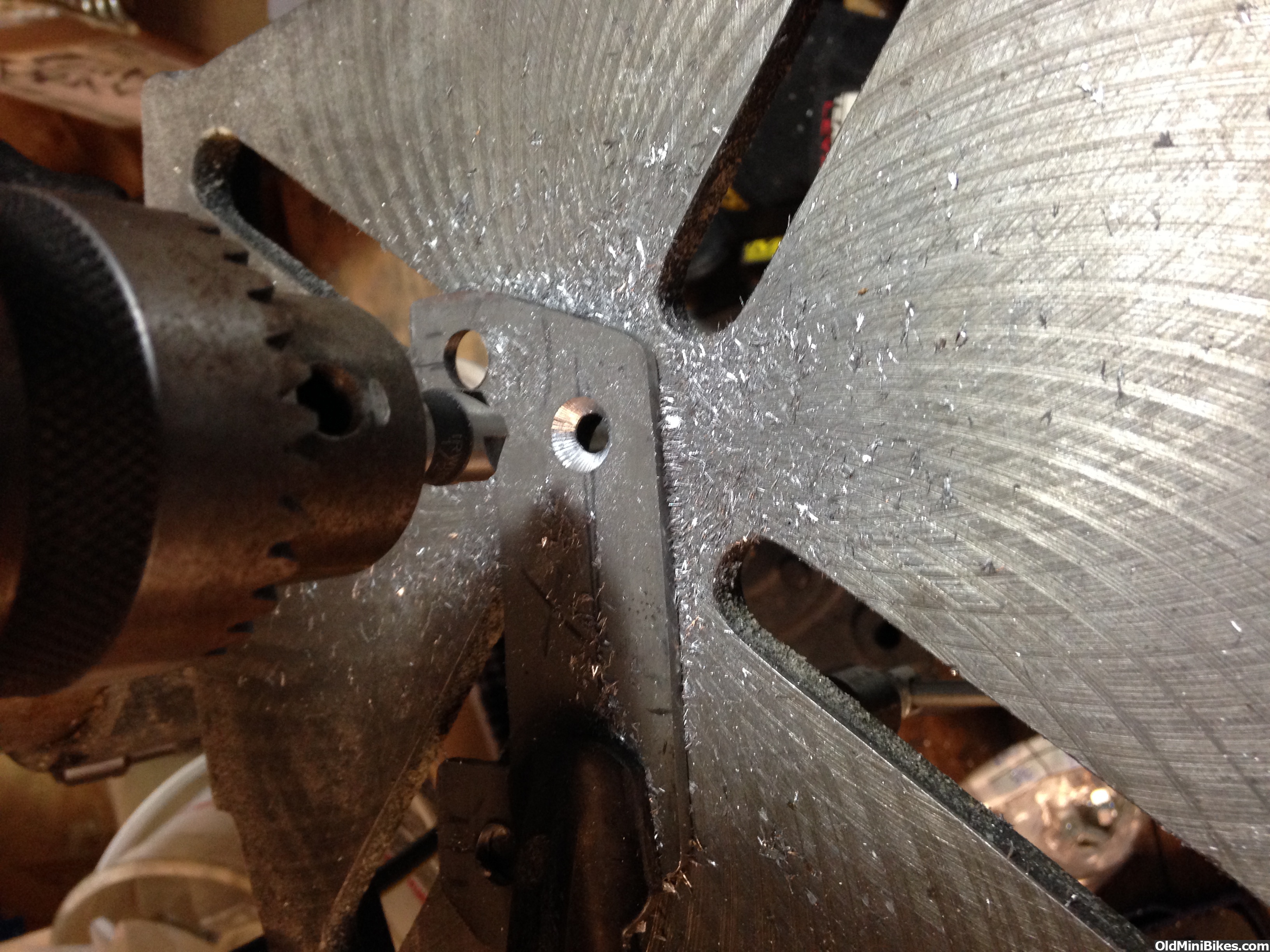
I countersunk screw holes to locate the solenoid on the plate.

Here it is mocked up on the replacement H60 for Wilderness (the HS50 goes on a new toy):

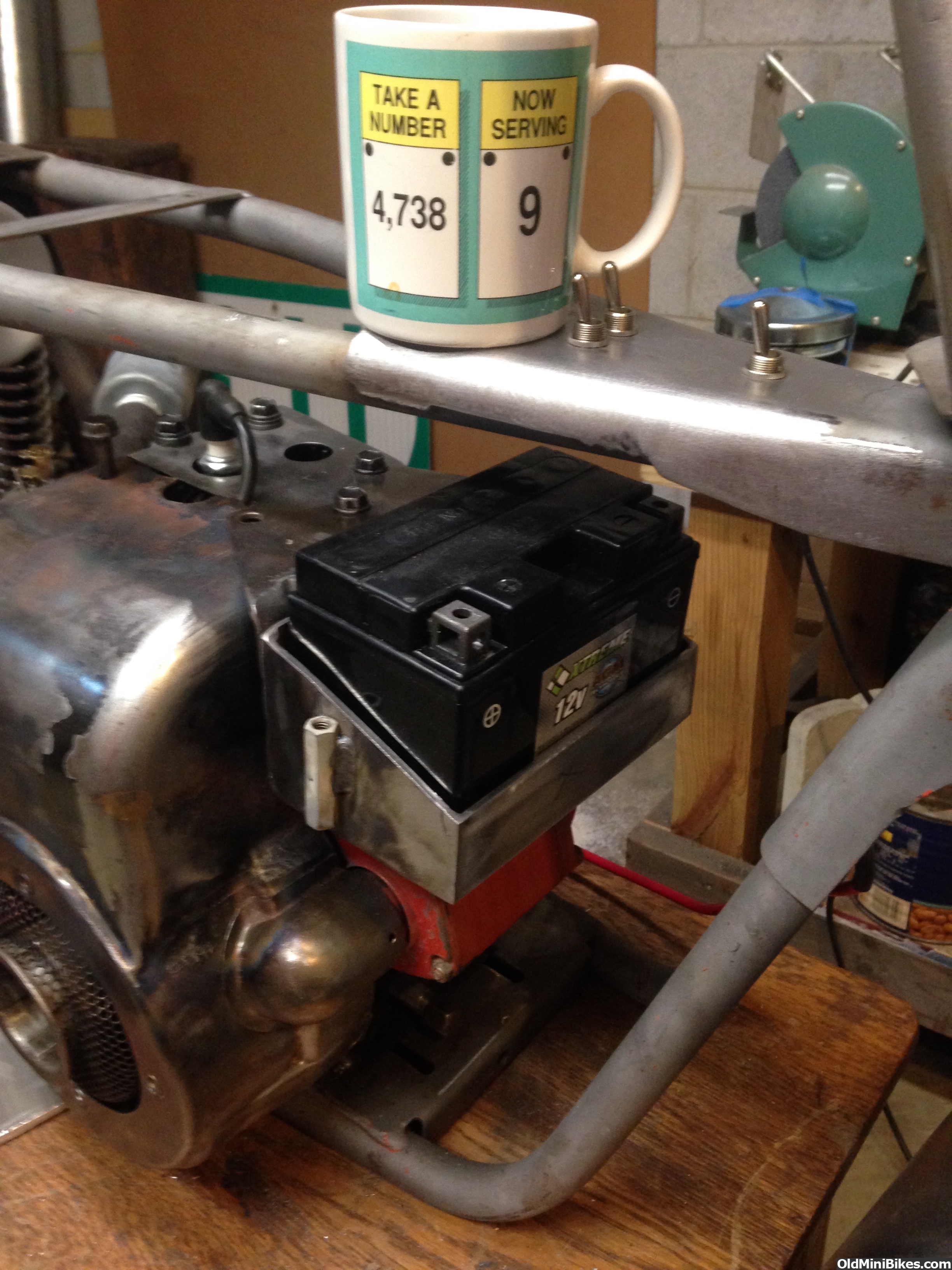
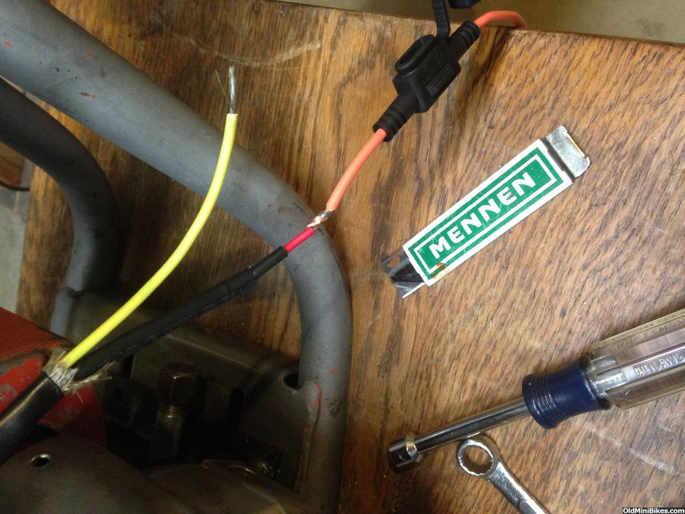
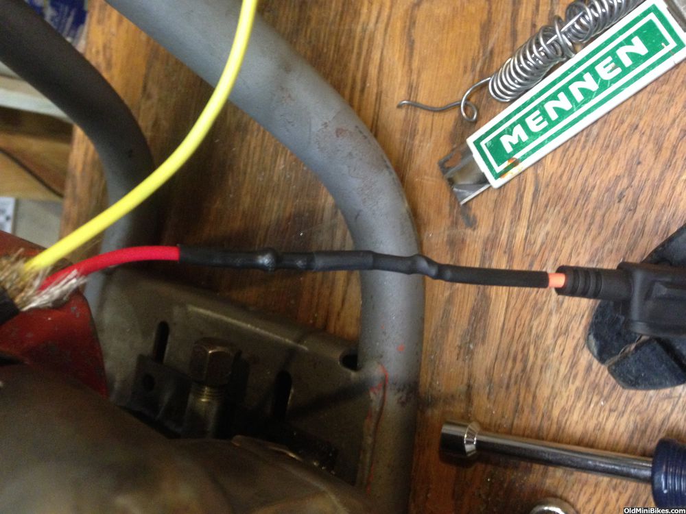
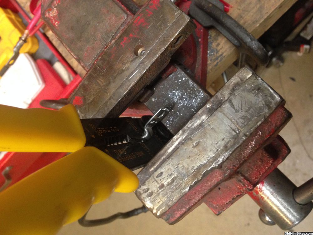
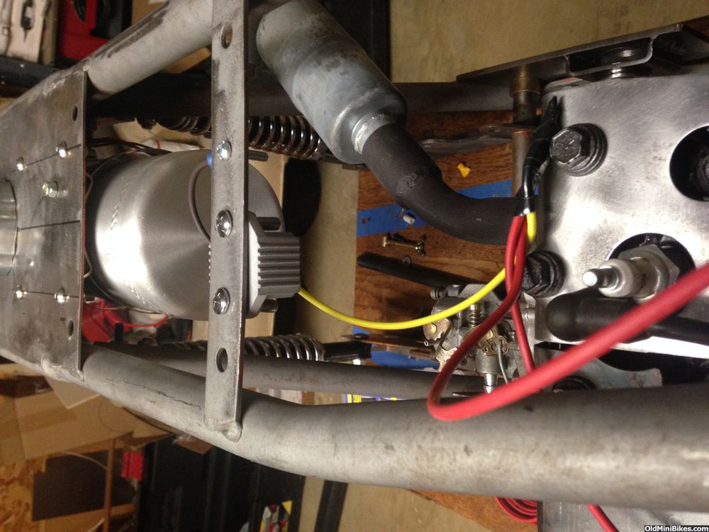
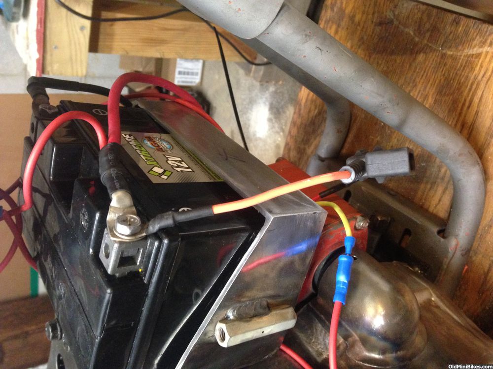
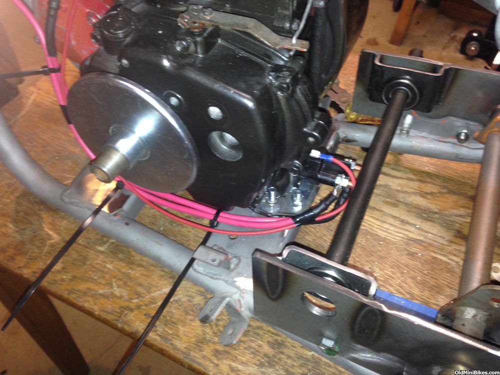
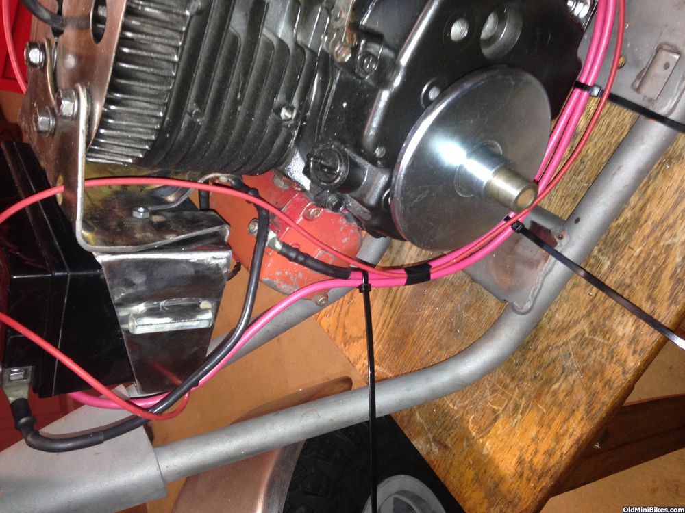
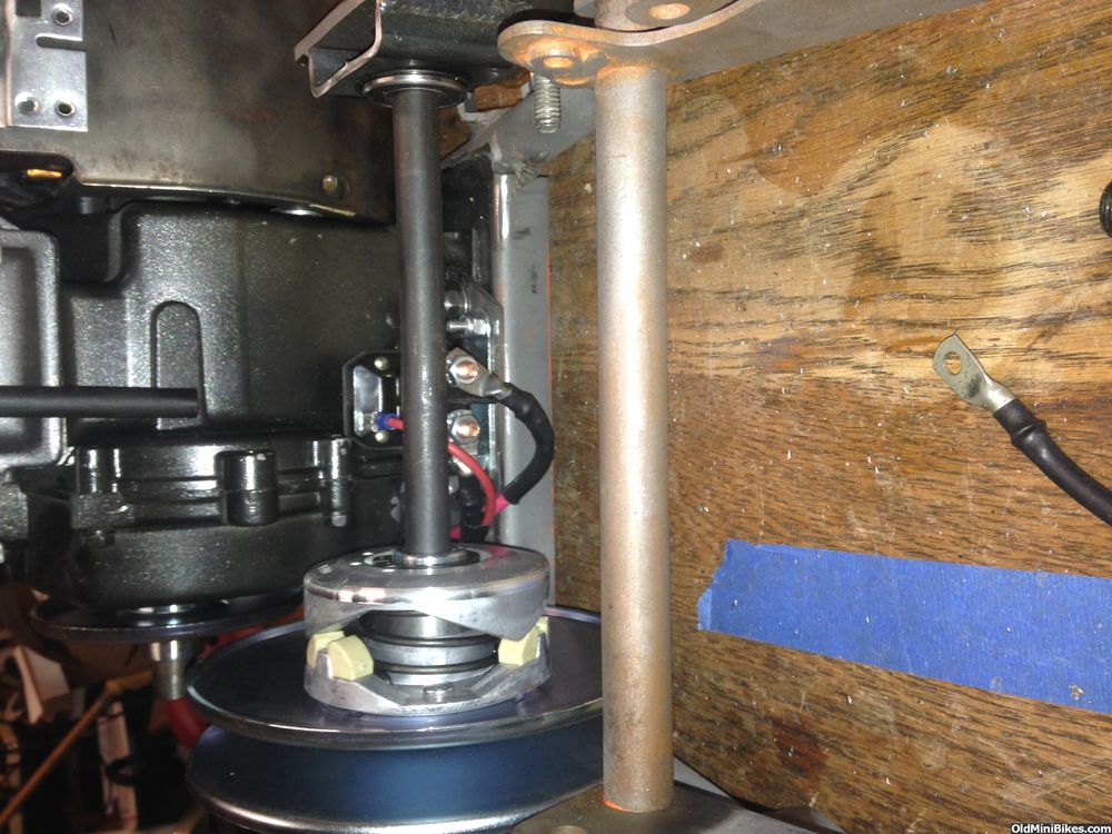
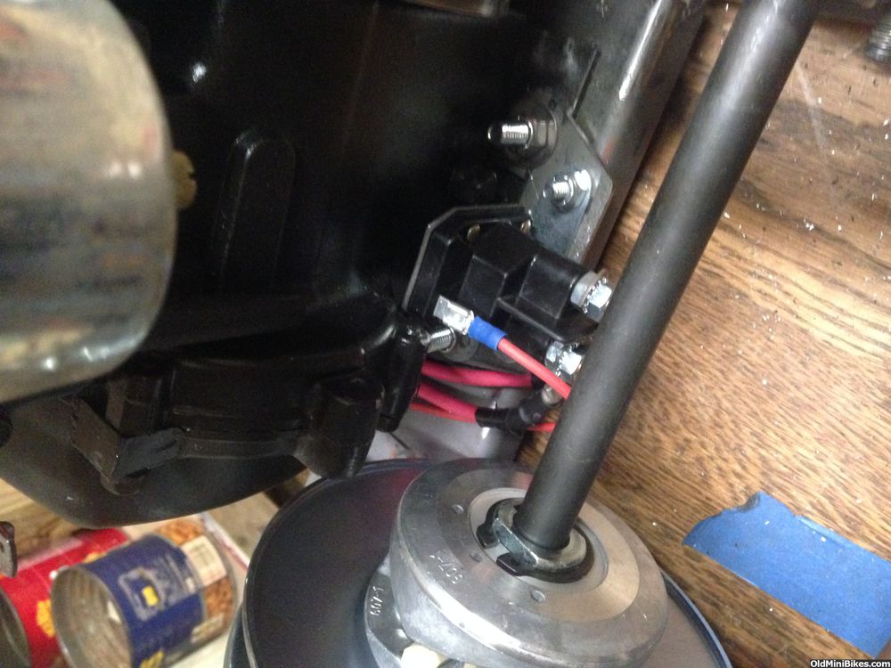
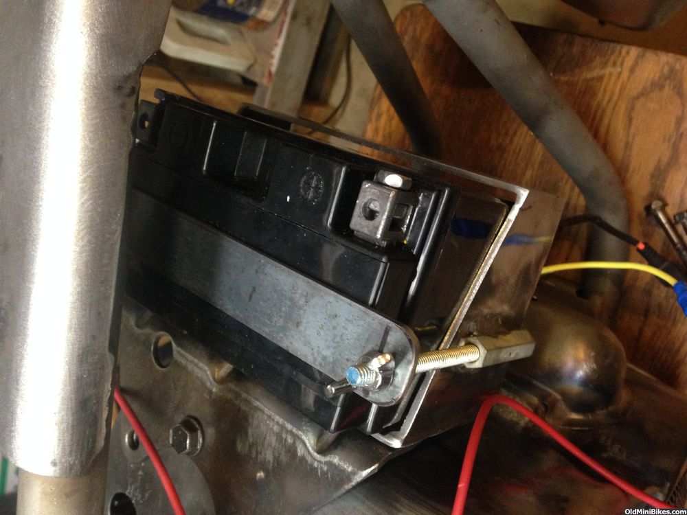
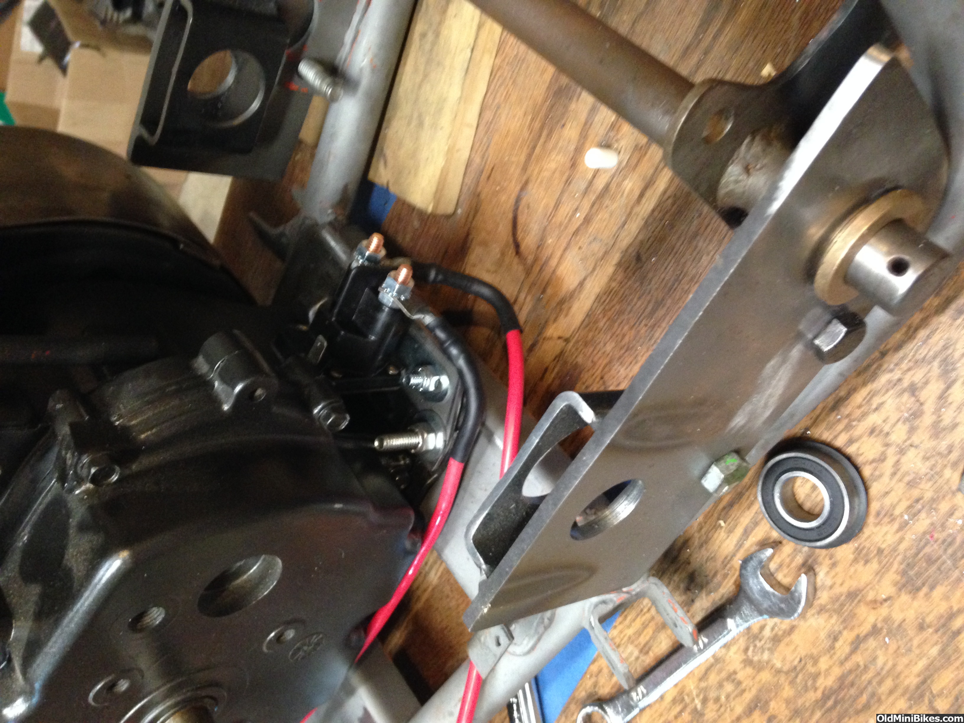
After that was done, I located it on the bike's Franken Motor. It fits below the jackshaft and away from the Driven Clutch. Should have no clearance issues, though I did get insulator caps for lugs on the solenoid. I made up battery to starter cables using 6 AWG copper wire and lugs, soldered the wire in place in the lug and used heat shrink tubing.

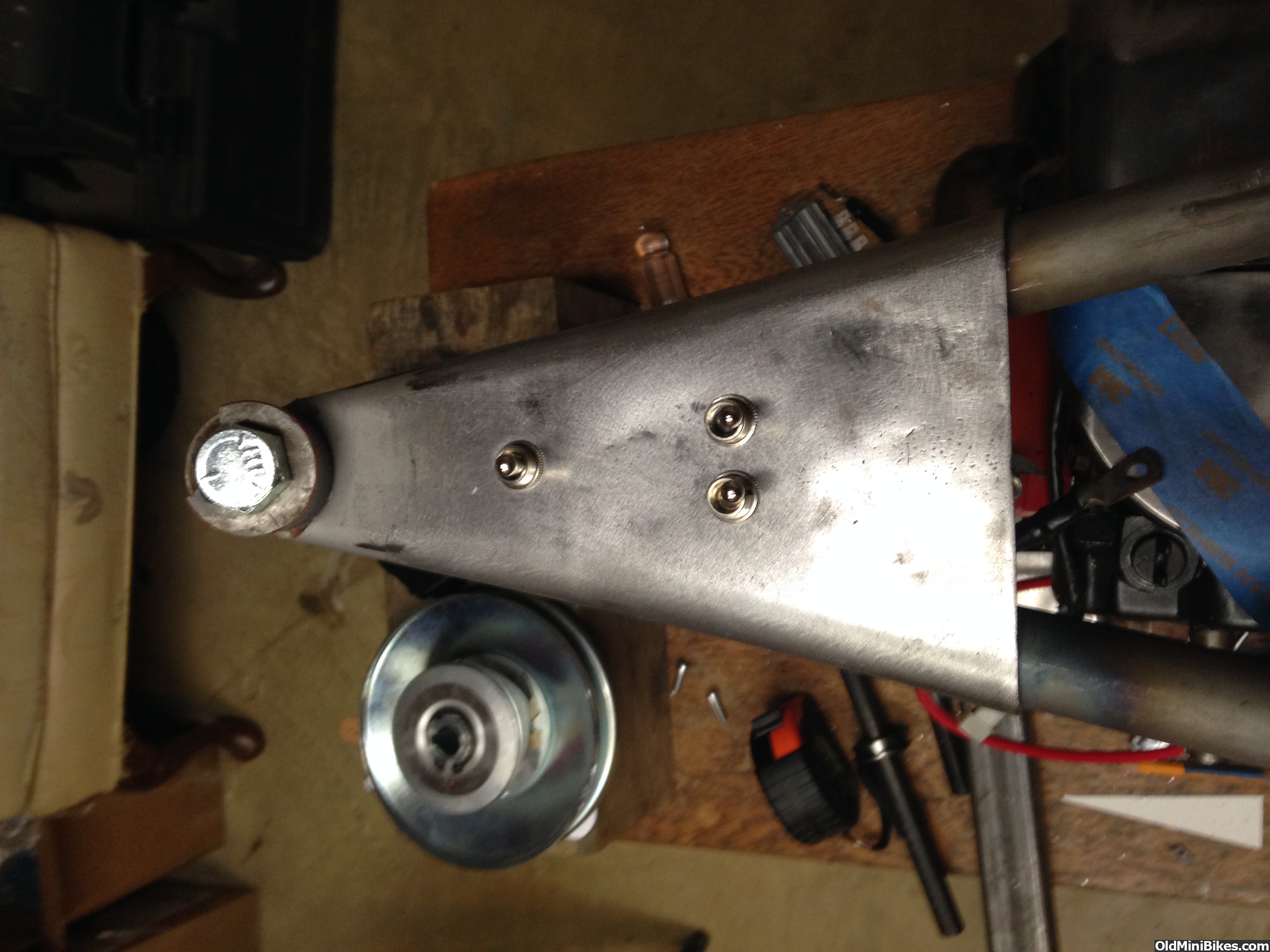
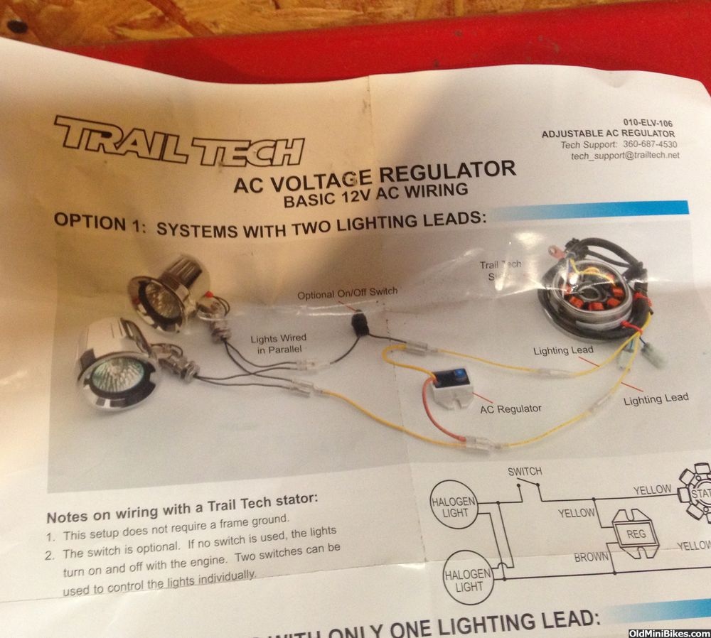
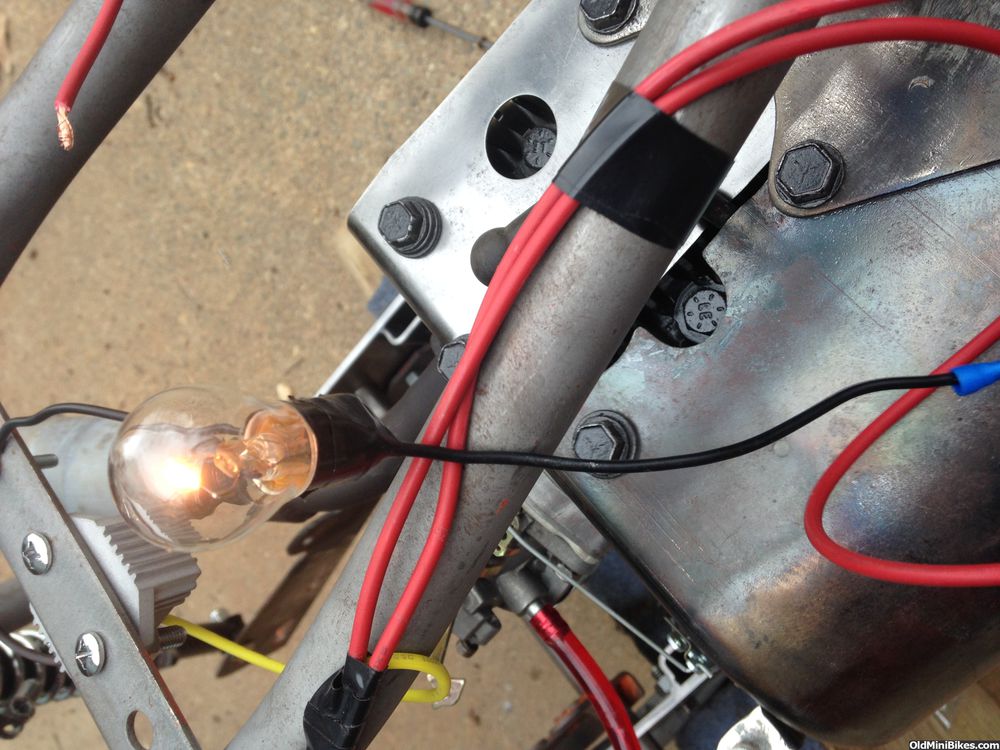
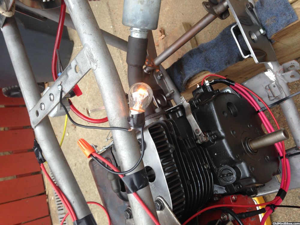
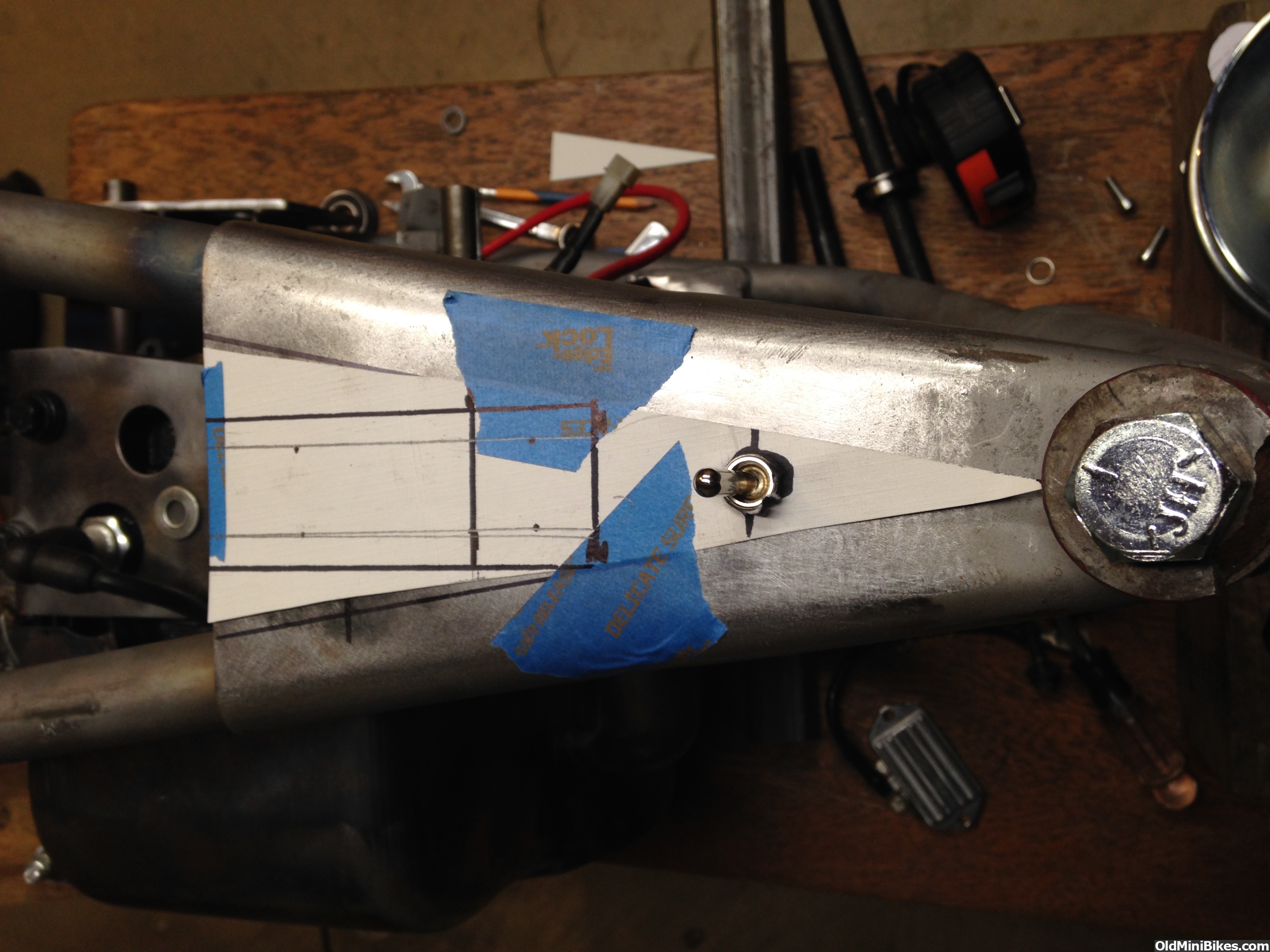
Next up were the switches. I abandoned the idea of using a key switch due to space considerations. Instead, I'm using a heavy duty momentary switch to operate the starter (DC side). On the AC side, I'm using a heavy duty switch for the lights and another heavy duty one for the kill switch.
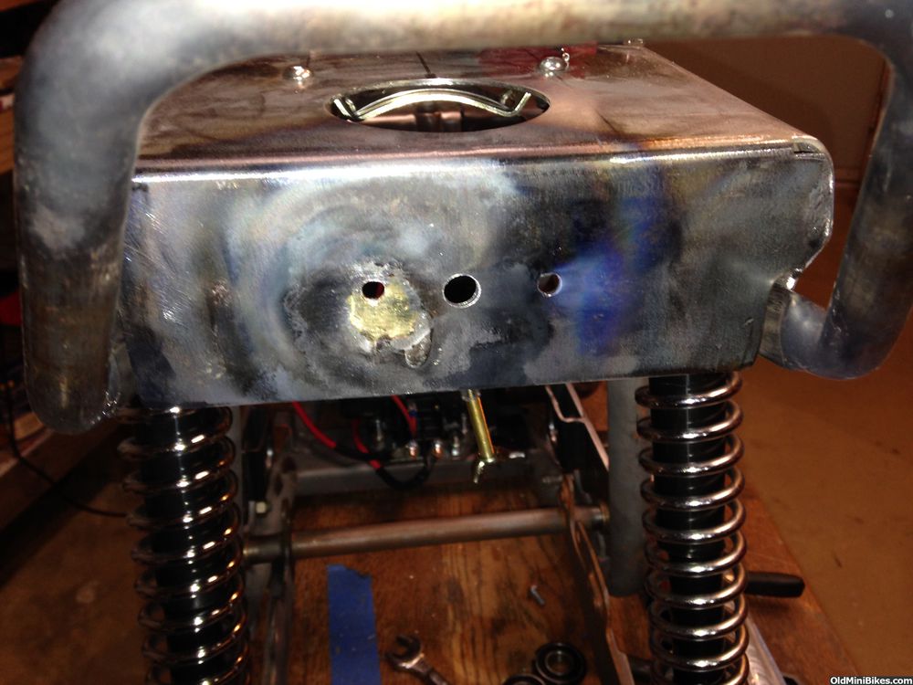
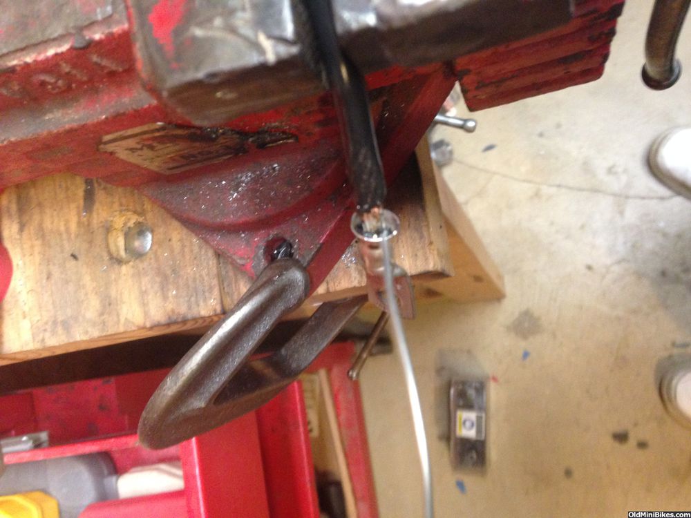
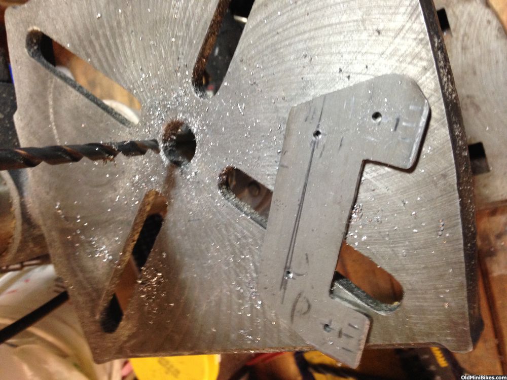
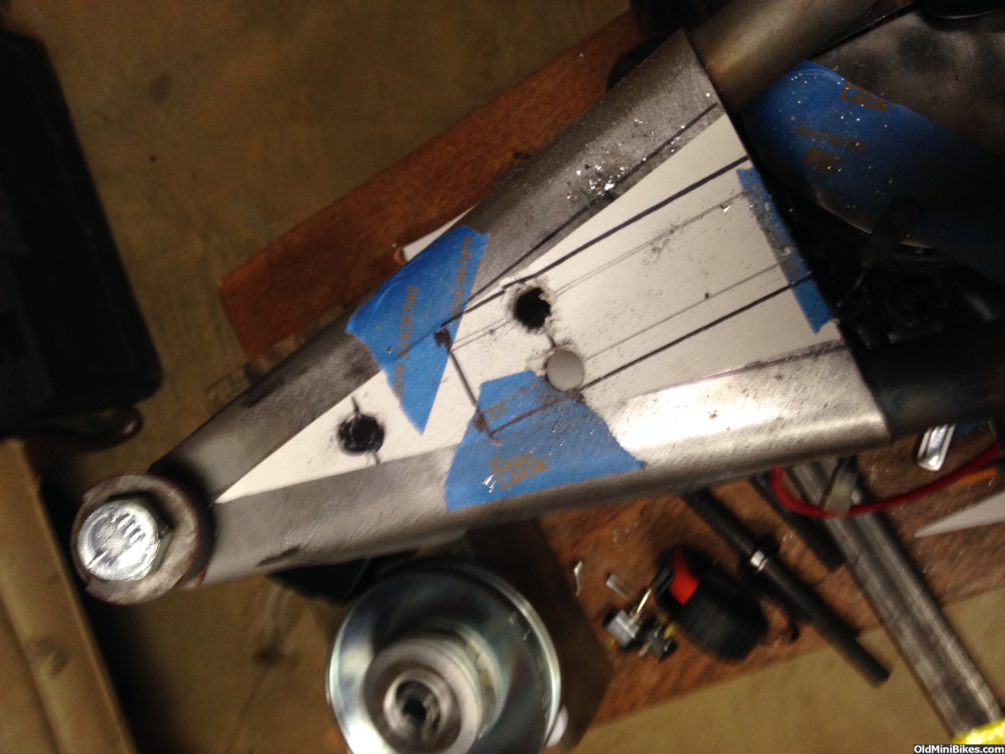
I made a template to locate the switches. Because these are heavy duty to handle amperage, they are pretty big, so locating them was a challenge.

1/8" pilot holes and then I drilled to size (while opening up just a tad for the powdercoat.)

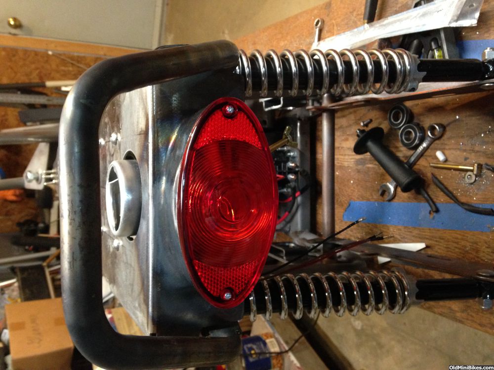
The kill switch remains in it's original location while the lights and starter switches are paired together. In a lot of ways, this is a good thing as one wouldn't want to fumble around for the kill switch in the event of a spill.

Was waiting for the big parts to come in, so I started on the wiring for starting and lighting. Because the bike will be powdercoated, I need to locate as much as I can close to the engine or on the engine to ensure I have good grounds. The solenoid is an ugly looking part, so I needed to hide it as best as I can.
I made a mounting plate that fits to the engine bottom plate. It's an odd looking shape, but that's because the bottom plate has some stampings I had to work around.
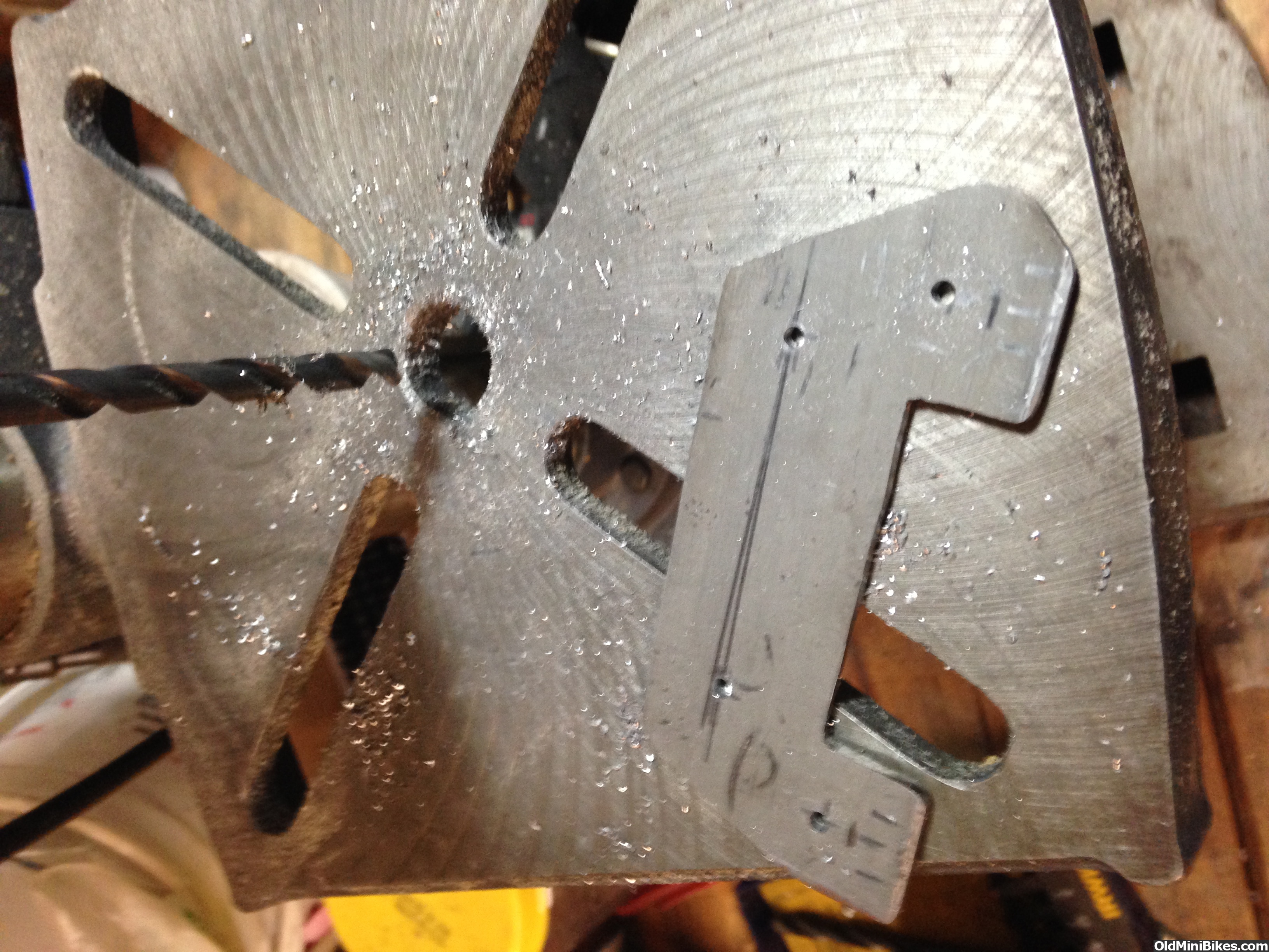
I countersunk screw holes to locate the solenoid on the plate.
Here it is mocked up on the replacement H60 for Wilderness (the HS50 goes on a new toy):
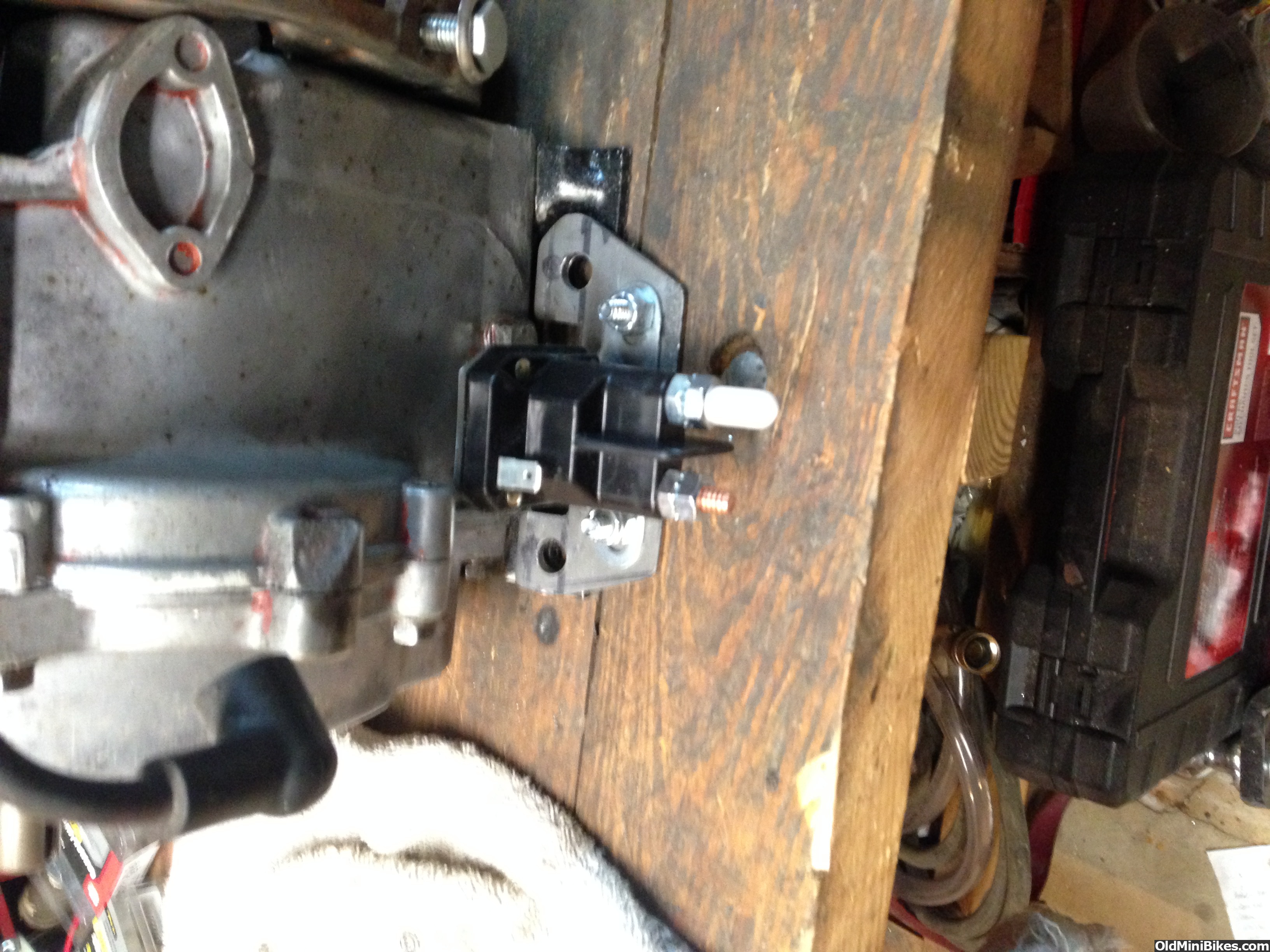
After that was done, I located it on the bike's Franken Motor. It fits below the jackshaft and away from the Driven Clutch. Should have no clearance issues, though I did get insulator caps for lugs on the solenoid. I made up battery to starter cables using 6 AWG copper wire and lugs, soldered the wire in place in the lug and used heat shrink tubing.
Next up were the switches. I abandoned the idea of using a key switch due to space considerations. Instead, I'm using a heavy duty momentary switch to operate the starter (DC side). On the AC side, I'm using a heavy duty switch for the lights and another heavy duty one for the kill switch.
I made a template to locate the switches. Because these are heavy duty to handle amperage, they are pretty big, so locating them was a challenge.
1/8" pilot holes and then I drilled to size (while opening up just a tad for the powdercoat.)
The kill switch remains in it's original location while the lights and starter switches are paired together. In a lot of ways, this is a good thing as one wouldn't want to fumble around for the kill switch in the event of a spill.