
You, Sir, sound like one crazy fella. I hope I get to run into you one day. That sure must have been one tough car. I had a 78 Impala that I just couldn't kill. Dropped an old LT1 in it and fed it a steady diet of nitrous. It ate pistons on the best runs. I never broke a block like that though! You're my hero!
Bet you wish you still had that old girl...
Joe
Bet you wish you still had that old girl...
Joe
Doug
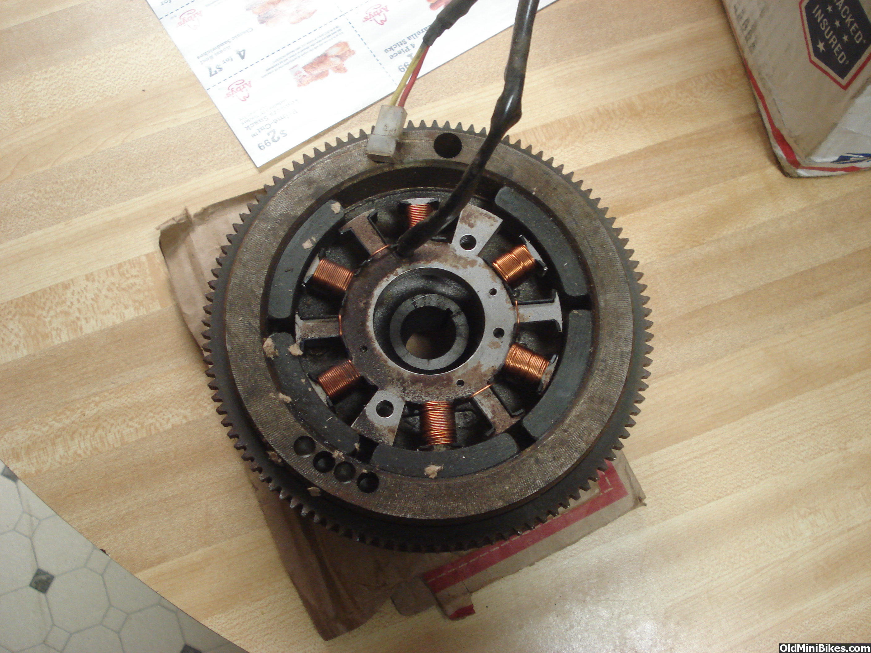
Can somebody tell me exactly what the output of this setup would be? And I assume that it would need a voltage regulator wired in?
Thanks,
Doug
Thanks,
Doug
There is a whole of information in the shop manual. I'd start there. I do know they varied depending on the application: charging circuit Y/N, aux Y/N, lights F/R. I. E., A flywheel/coil for a Wheelhorse application would include a charging circuit. The output would vary accordingly.
Doug,
There is a whole of information in the shop manual. I'd start there. I do know they varied depending on the application: charging circuit Y/N, aux Y/N, lights F/R. I. E., A flywheel/coil for a Wheelhorse application would include a charging circuit. The output would vary accordingly.
There is a whole of information in the shop manual. I'd start there. I do know they varied depending on the application: charging circuit Y/N, aux Y/N, lights F/R. I. E., A flywheel/coil for a Wheelhorse application would include a charging circuit. The output would vary accordingly.
charging circuit Y/N, aux Y/N, lights F/R. I. E., A flywheel/coil :shrug:
It only has 2 wires..... This is not my strong suite yet. Its an HM 80 / HM100 application.
The guy said that he thought he had more 3 magnet flywheels but wasn't sure if he had another 5 magnet.
Thanks,
Doug
Doug, I did some digging around.
It looks like you have PN 611104 Alternator, which plugs in to 611175 Regulator/Rectifier. The red wire should be 13 volts DC at 3600 RPM with a capacity of 3 amps. It has a diode. The yellow wire should be 13 volts AC at 3600 RPM with a capacity of 5 amps.
I am not sure how "that" regulator/rectifier is hooked into the rest of the system.
Later on in the book, different values are given. There is a lot to be desired in some of the Tecumseh manuals. If you were to strip back the wiring loom, (I wouldn't) you'd see that diode, but you may be able to feel it as a lump. It will be on the DC side always on every version, since it is what "cuts off" the negative side of the voltage. (remembering of course that all Tecumseh charging and light systems are AC)
This is the on line publication I looked at. Hopefully it will help.
https://www.smallenginesuppliers.com/html/engine-specs/tecumseh/Tecumseh_quick_reference.pdf
It seems to me, that you might be able to cut off the corresponding fin on the other side.
I doubt it would make make much difference in cooling, and it would sill be balanced.
Or would it?
I doubt it would make make much difference in cooling, and it would sill be balanced.
Or would it?
Thank you sir but could you translate that to English for dummies.......
charging circuit Y/N, aux Y/N, lights F/R. I. E., A flywheel/coil :shrug:
It only has 2 wires..... This is not my strong suite yet. Its an HM 80 / HM100 application.
The guy said that he thought he had more 3 magnet flywheels but wasn't sure if he had another 5 magnet.
Thanks,
Doug
charging circuit Y/N, aux Y/N, lights F/R. I. E., A flywheel/coil :shrug:
It only has 2 wires..... This is not my strong suite yet. Its an HM 80 / HM100 application.
The guy said that he thought he had more 3 magnet flywheels but wasn't sure if he had another 5 magnet.
Thanks,
Doug
Havasu Dave's referencer is best. My translation is charging circuit YES/NO, Lights Front/Rear, Auxiliary light/lighter/strobe Yes/No. "I.E." is the Latin abbreviation for "as an example." I seem to remember a comment by Dave that references changing the headlamp from 12 to 6v because at low rpm, the voltage output is lower. Similarly, the coil needs more windings for higher or additional current draws (amperage requirement goes up based on demand). Voltage is the pressure to push the current (amperage) needed for the powered items.
Thanks!
Doug
NOW.... That makes sense! I appreciate the explanation. I can follow that. :thumbsup: Thanks! Doug
To clarify six volt head lamps- I said that with regard to the tiny charging systems with no battery, no biasing diode, where the maximum voltage is 10. Use 6 volt incandescent bulbs for that, and 12 volt tail lamps for that.
In Doug's case with this engine, it's all 12 volt, all the time. I referenced the part number of the alternator and the reg./rectifier.
By the way Pete, your questionnaire is incomplete. You need to add "Hand Warmer" Y/N. From the various schematics I was researching, they are by far the highest loads.
Good job on describing voltage as "electrical pressure." Amperage is what happens when you turn on the tap and it flows.
Yeah, thanks Pete. FMTT, I only spent a half an hour researching Doug's question. It's all on page 3, before comments about cutting off fins came in to being.
To clarify six volt head lamps- I said that with regard to the tiny charging systems with no battery, no biasing diode, where the maximum voltage is 10. Use 6 volt incandescent bulbs for that, and 12 volt tail lamps for that.
In Doug's case with this engine, it's all 12 volt, all the time. I referenced the part number of the alternator and the reg./rectifier.
By the way Pete, your questionnaire is incomplete. You need to add "Hand Warmer" Y/N. From the various schematics I was researching, they are by far the highest loads.
Good job on describing voltage as "electrical pressure." Amperage is what happens when you turn on the tap and it flows.
Dave, My apologies for missing your post. I was hoping that you would chime in. I came back to the thread with a mention notification from the top of the page and didn't even realize that I had missed a page by doing that.
I thank you for the answer and the time you put in. I still don't have a solid grasp of this Tecumseh stuff but am trying to learn.
Thanks,
Doug
Dave, My apologies for missing your post. I was hoping that you would chime in. I came back to the thread with a mention notification from the top of the page and didn't even realize that I had missed a page by doing that. I thank you for the answer and the time you put in. I still don't have a solid grasp of this Tecumseh stuff but am trying to learn. Thanks, Doug