hemi head rework

#1
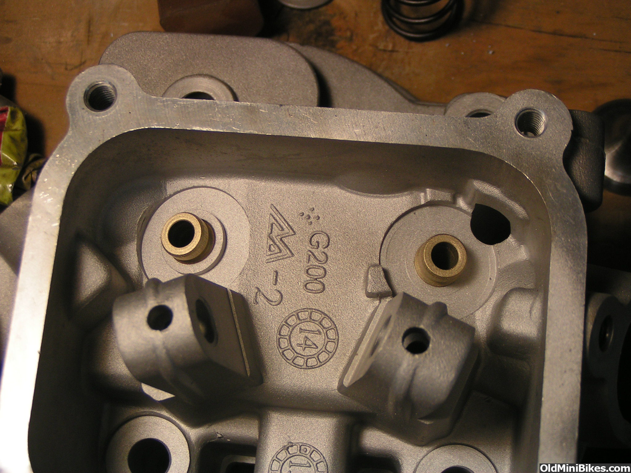
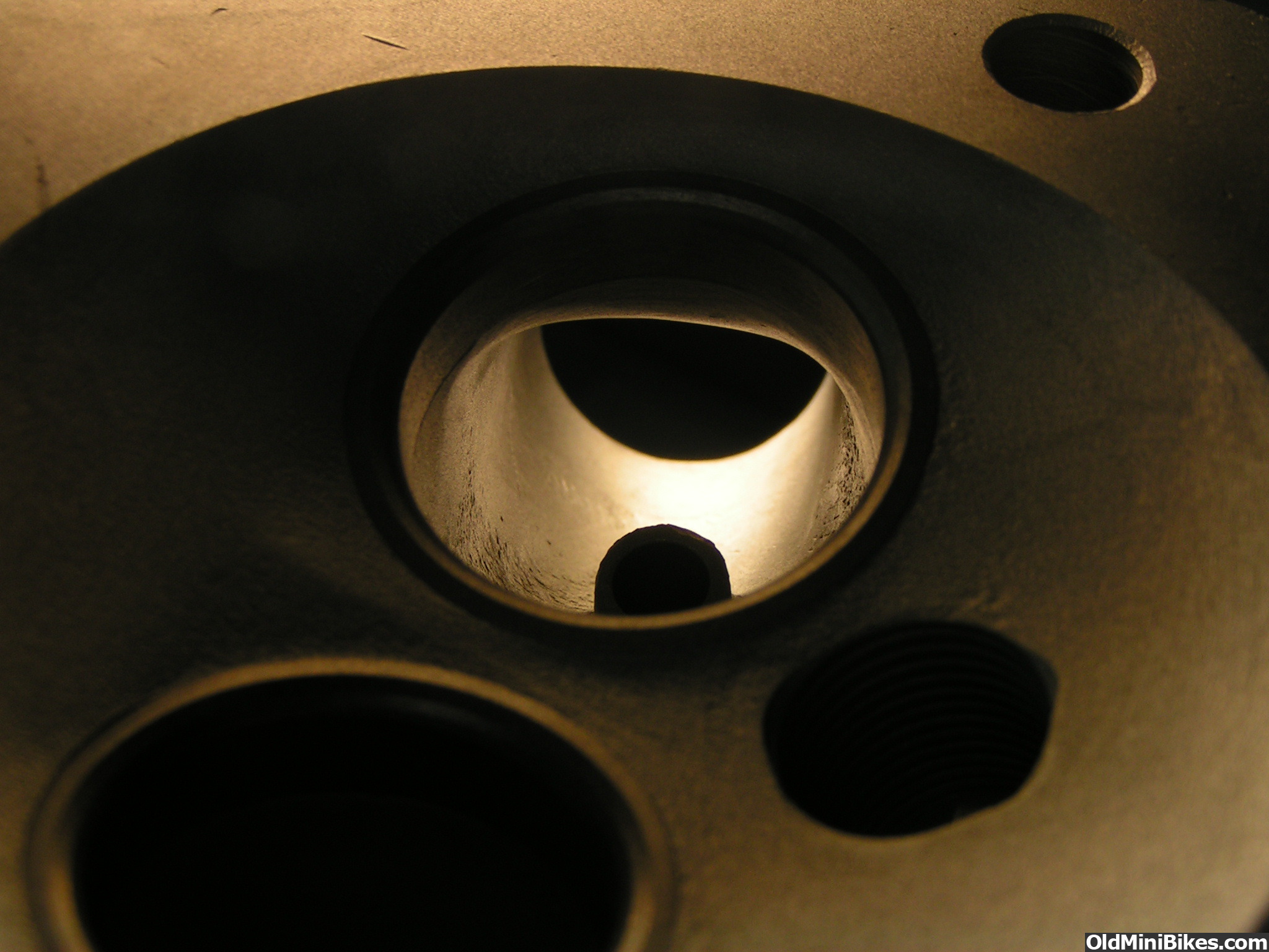
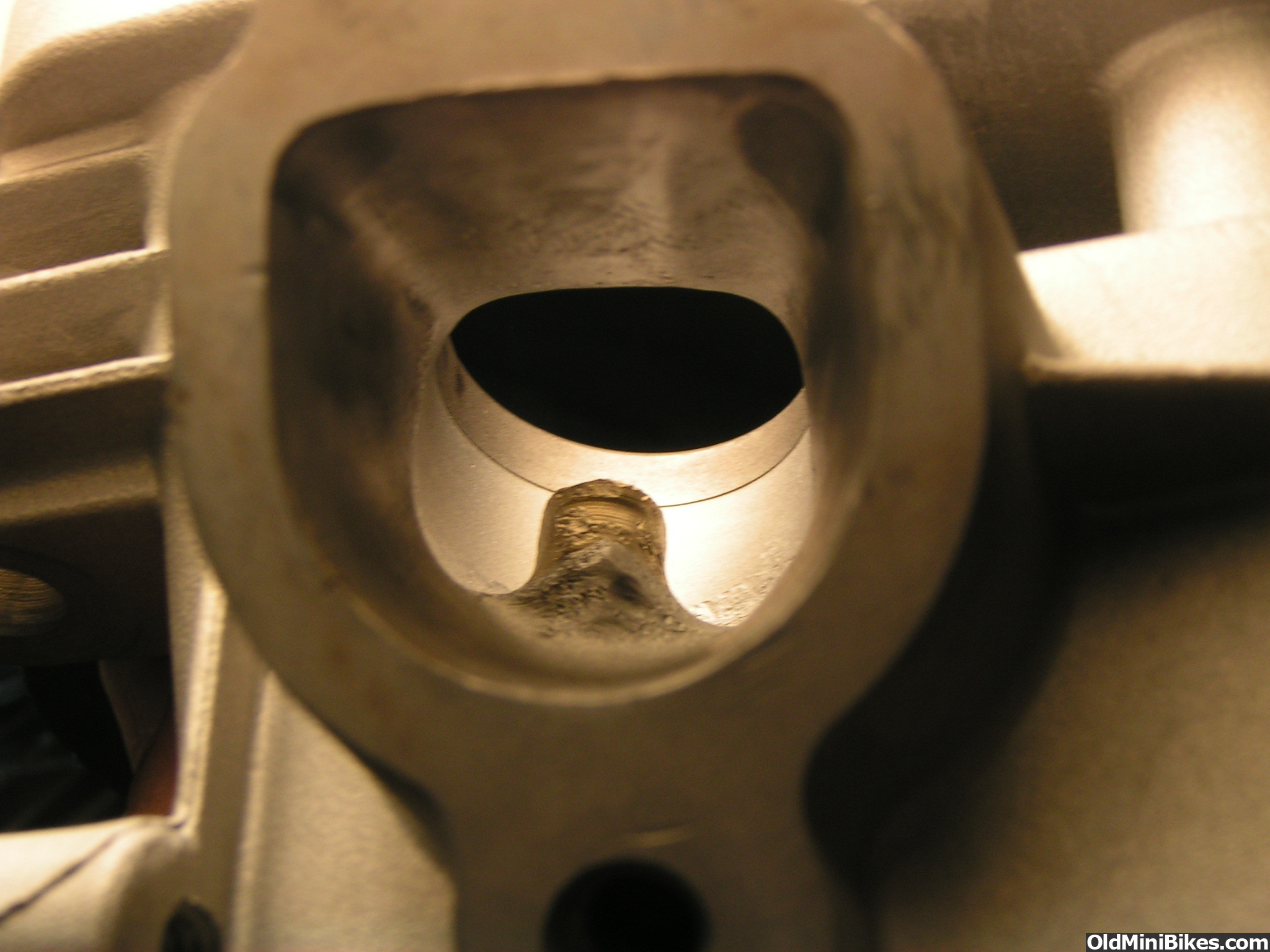
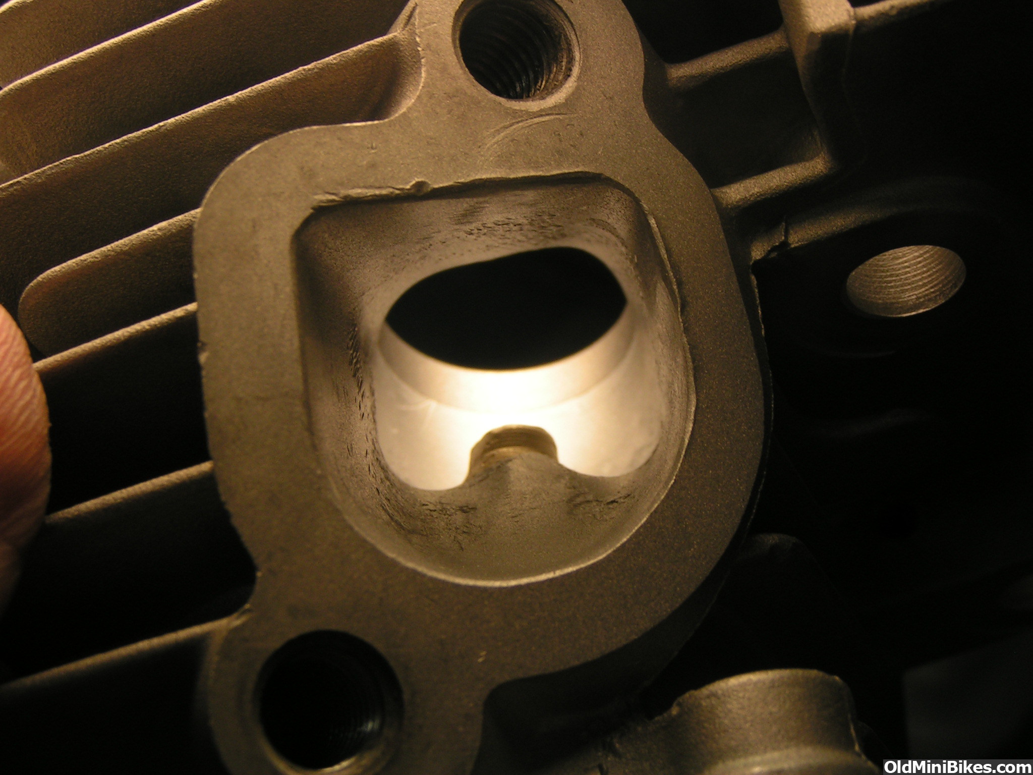
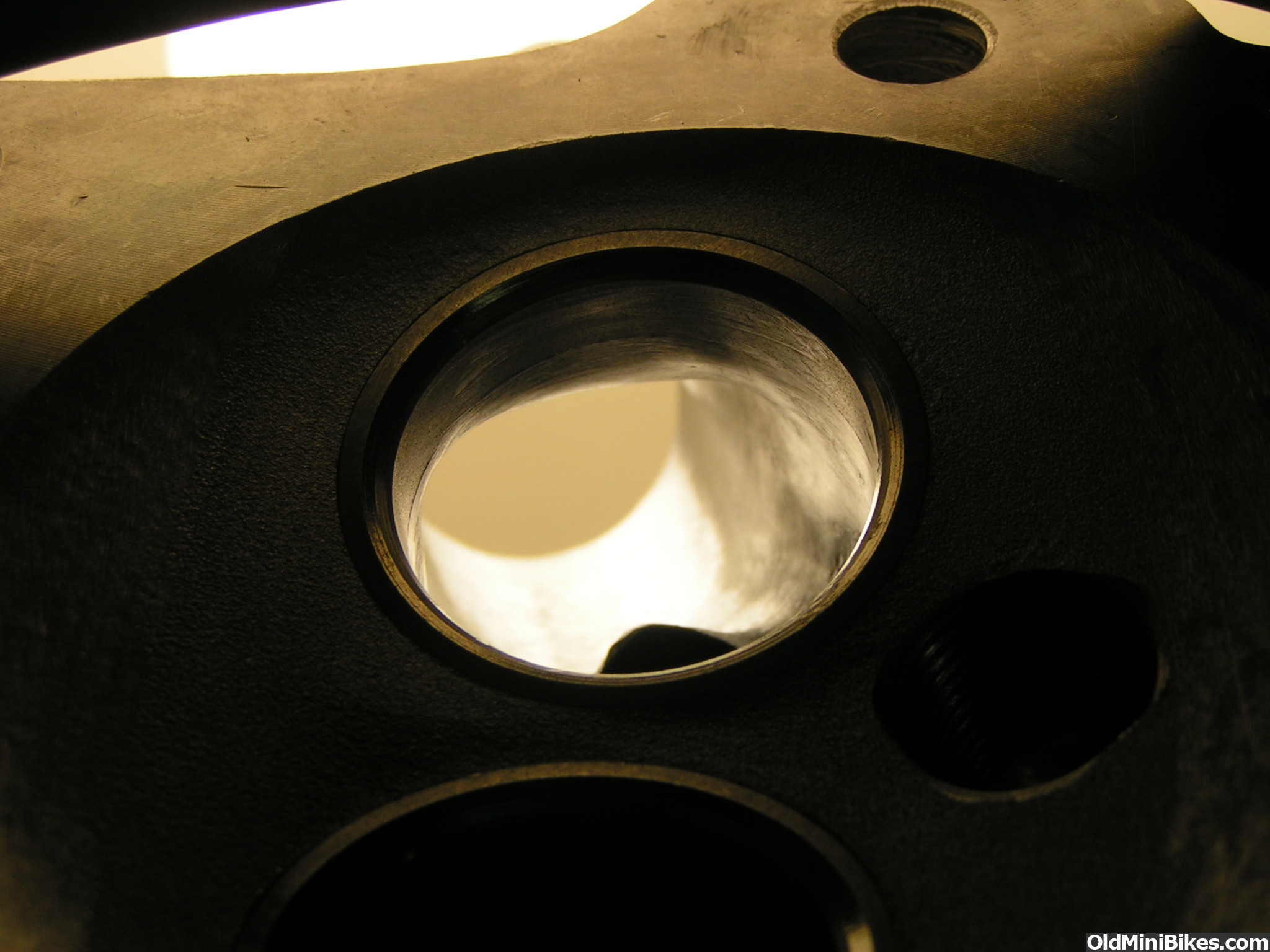
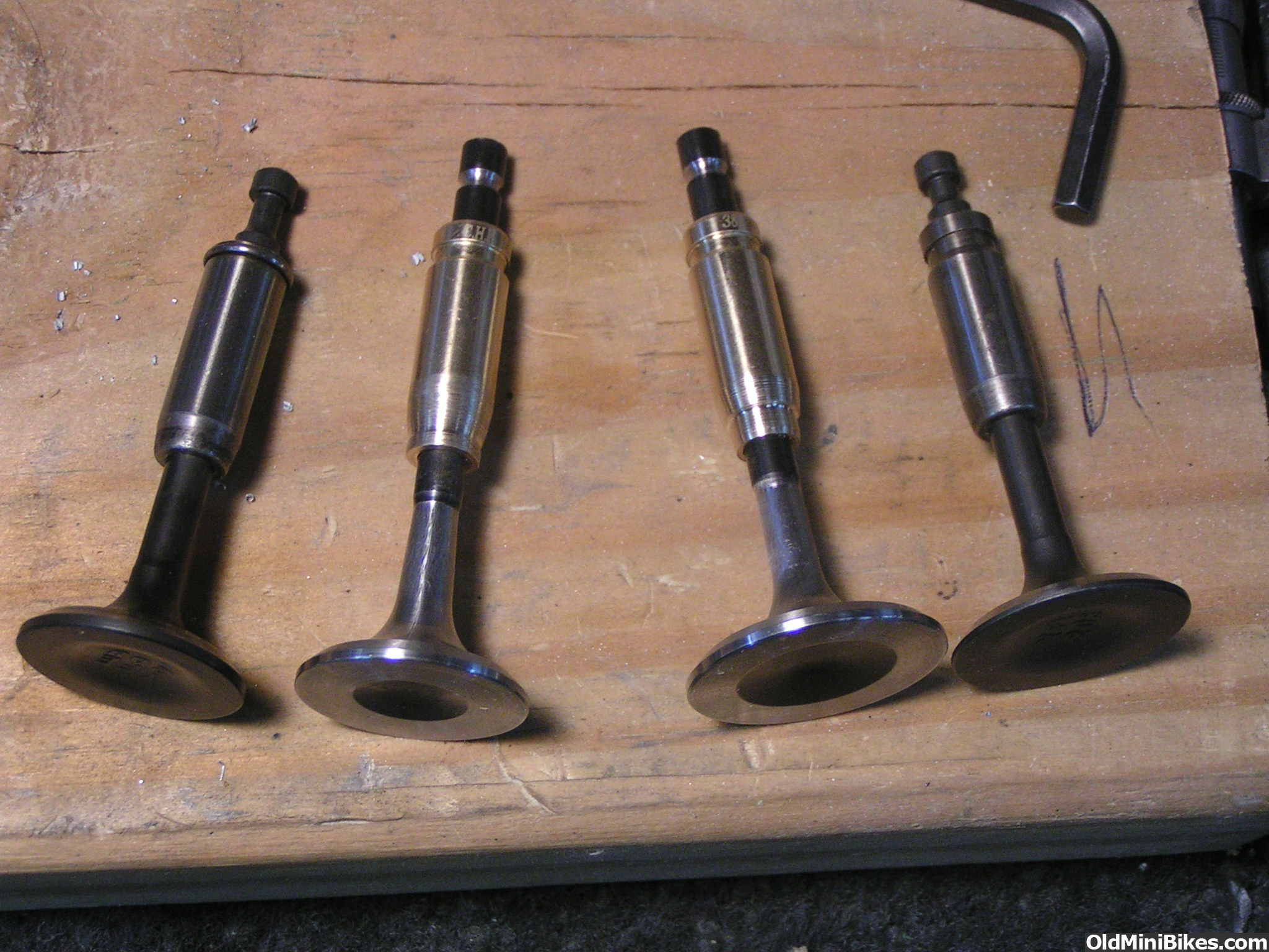
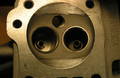
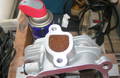
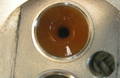
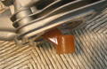
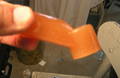
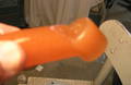
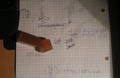
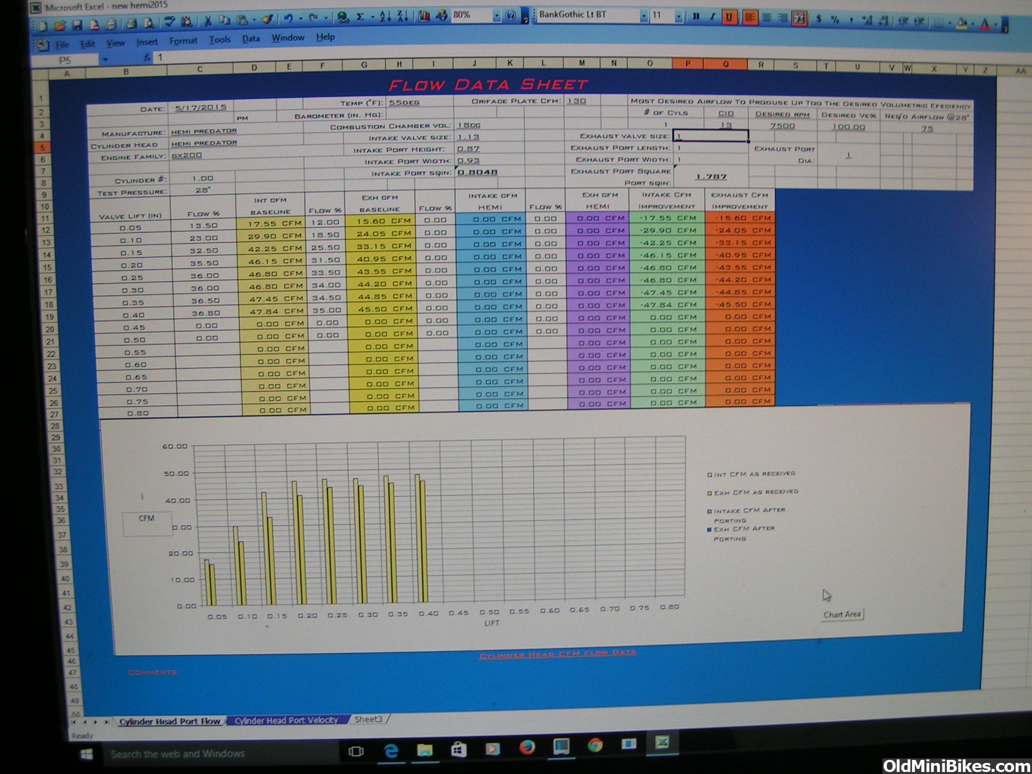
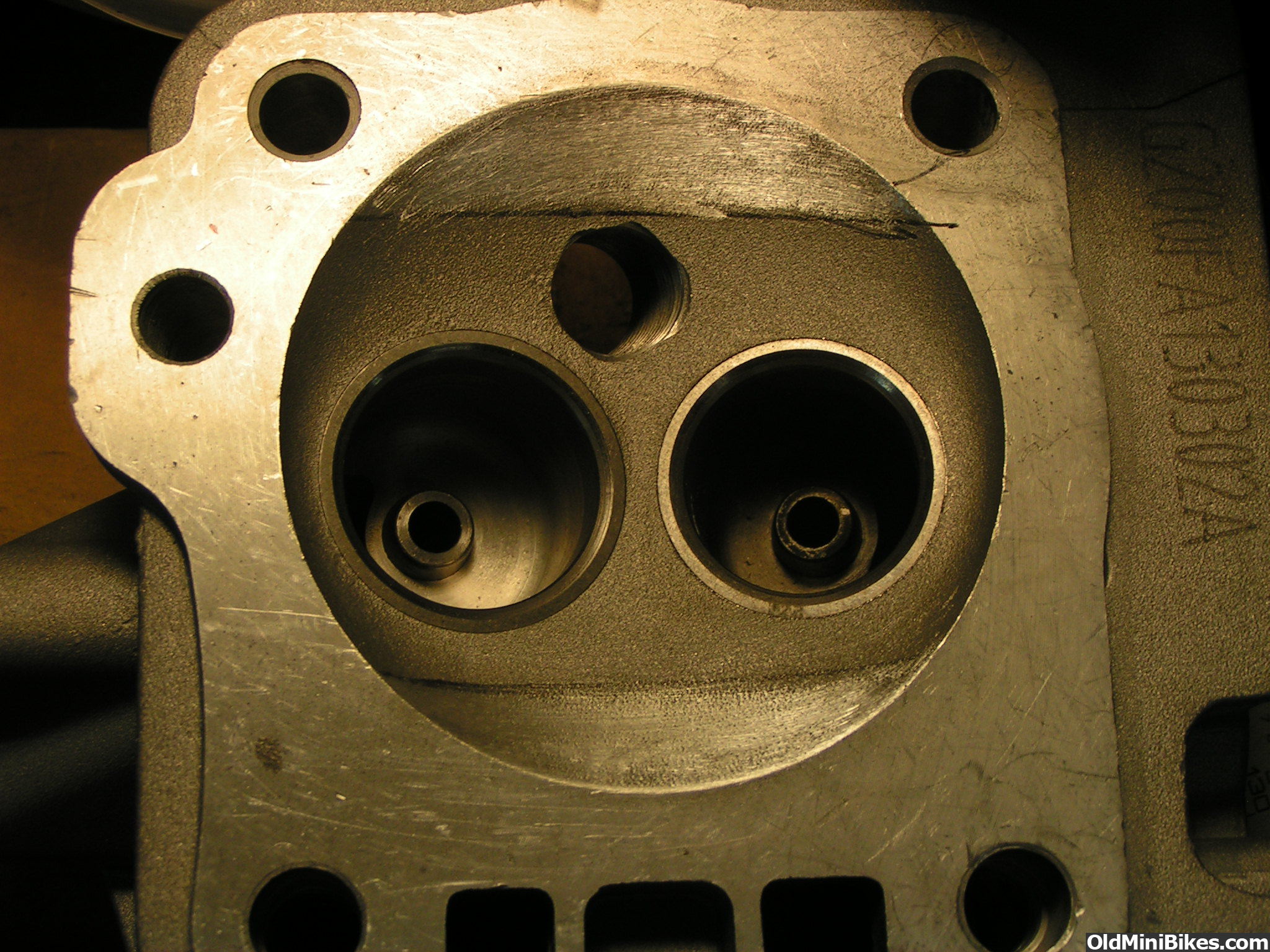
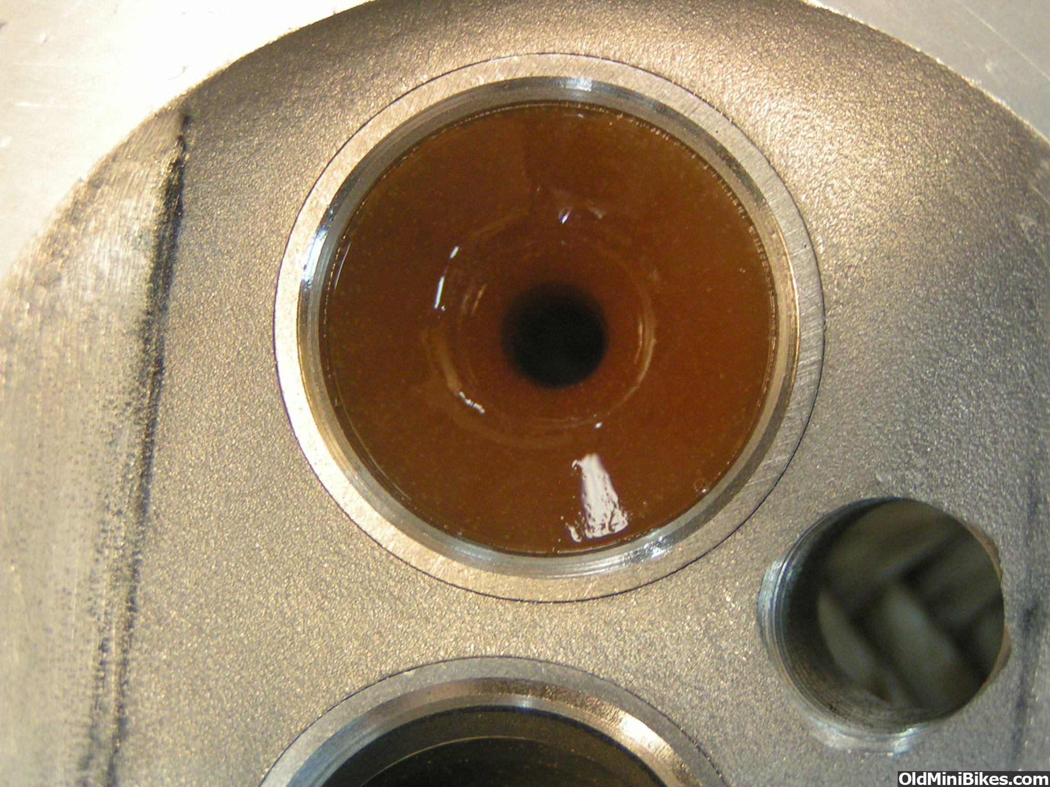
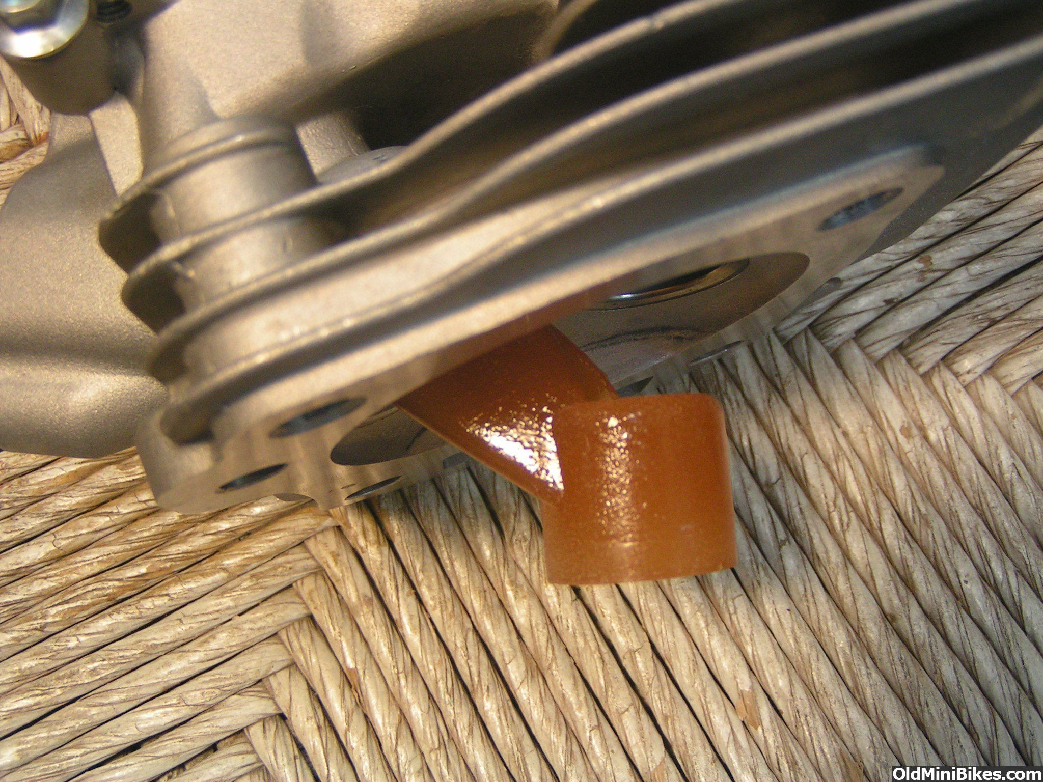
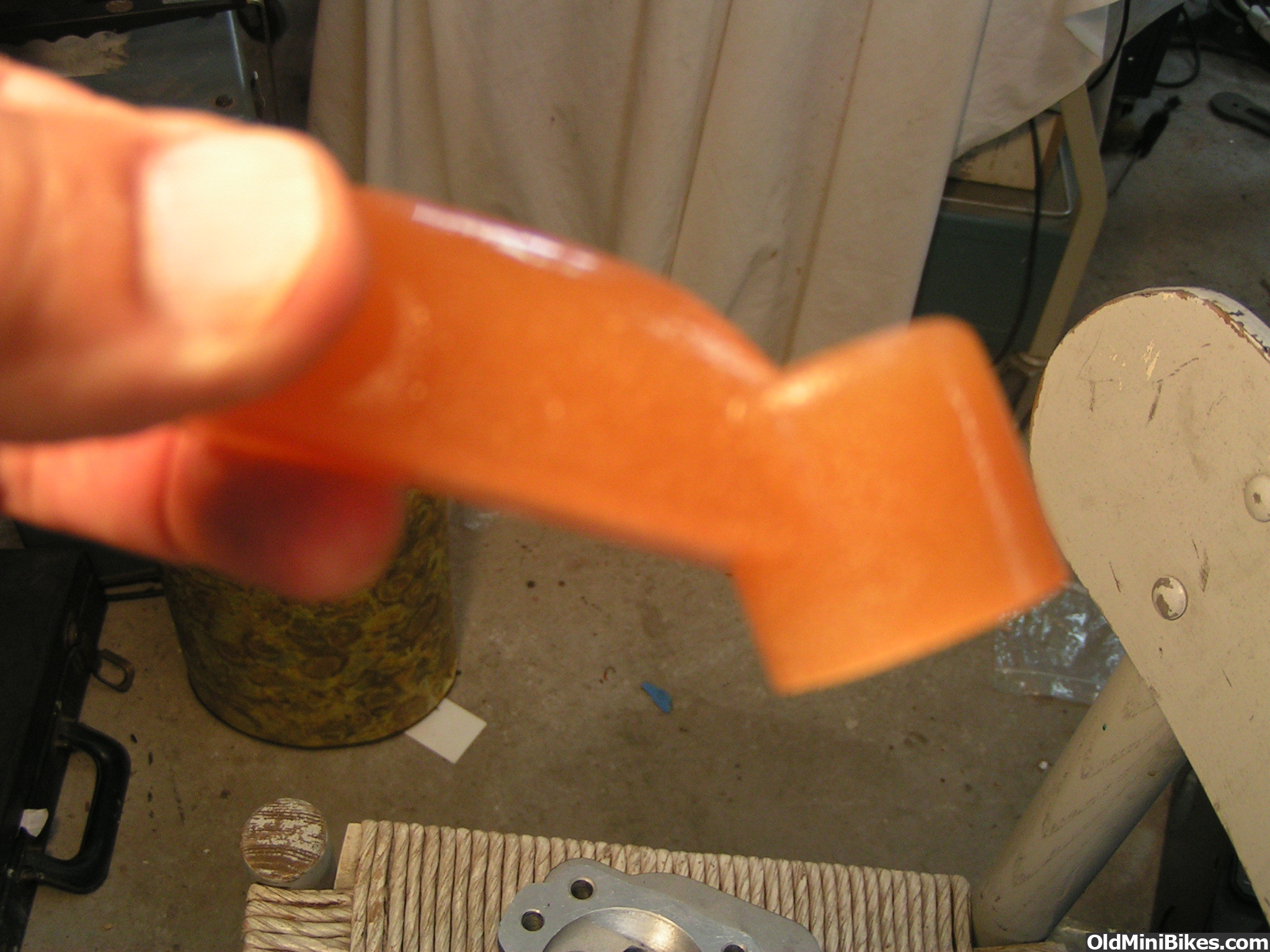
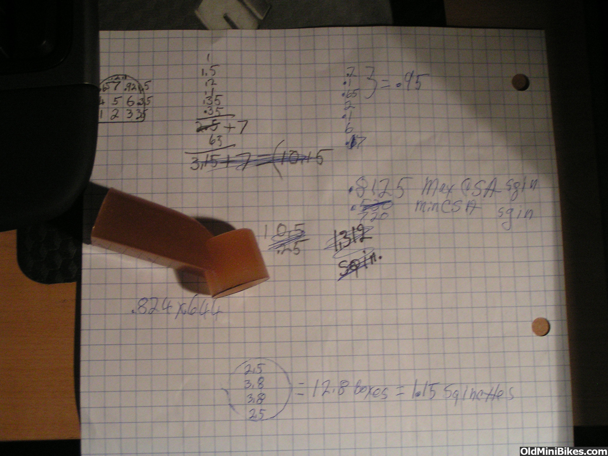
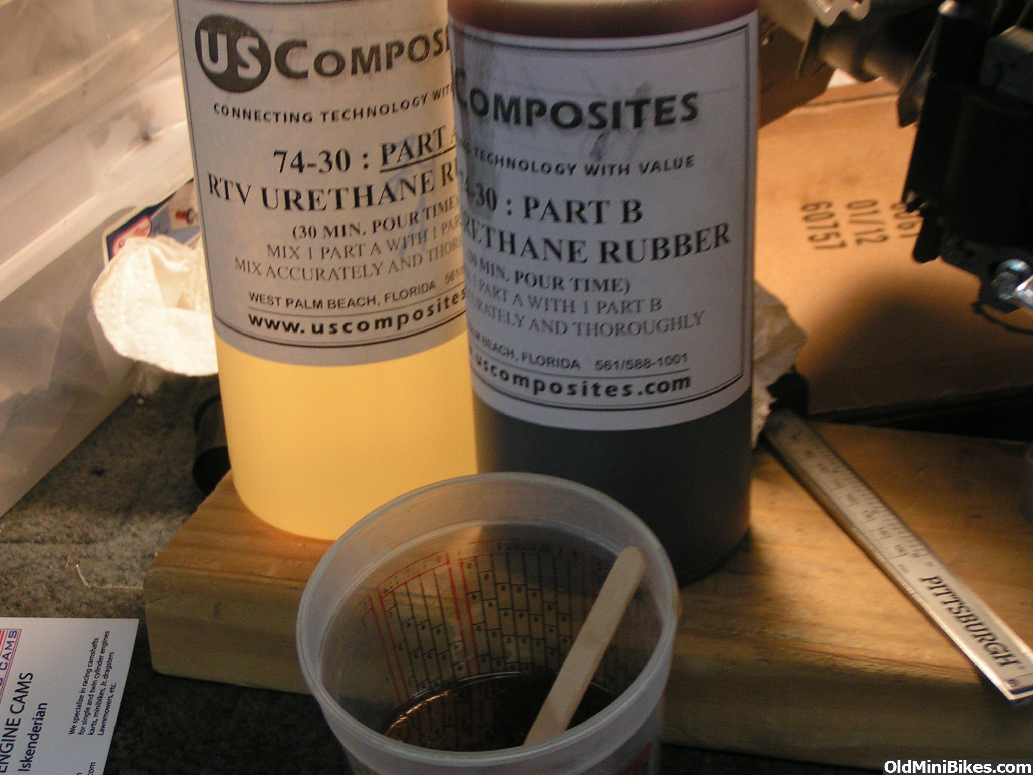
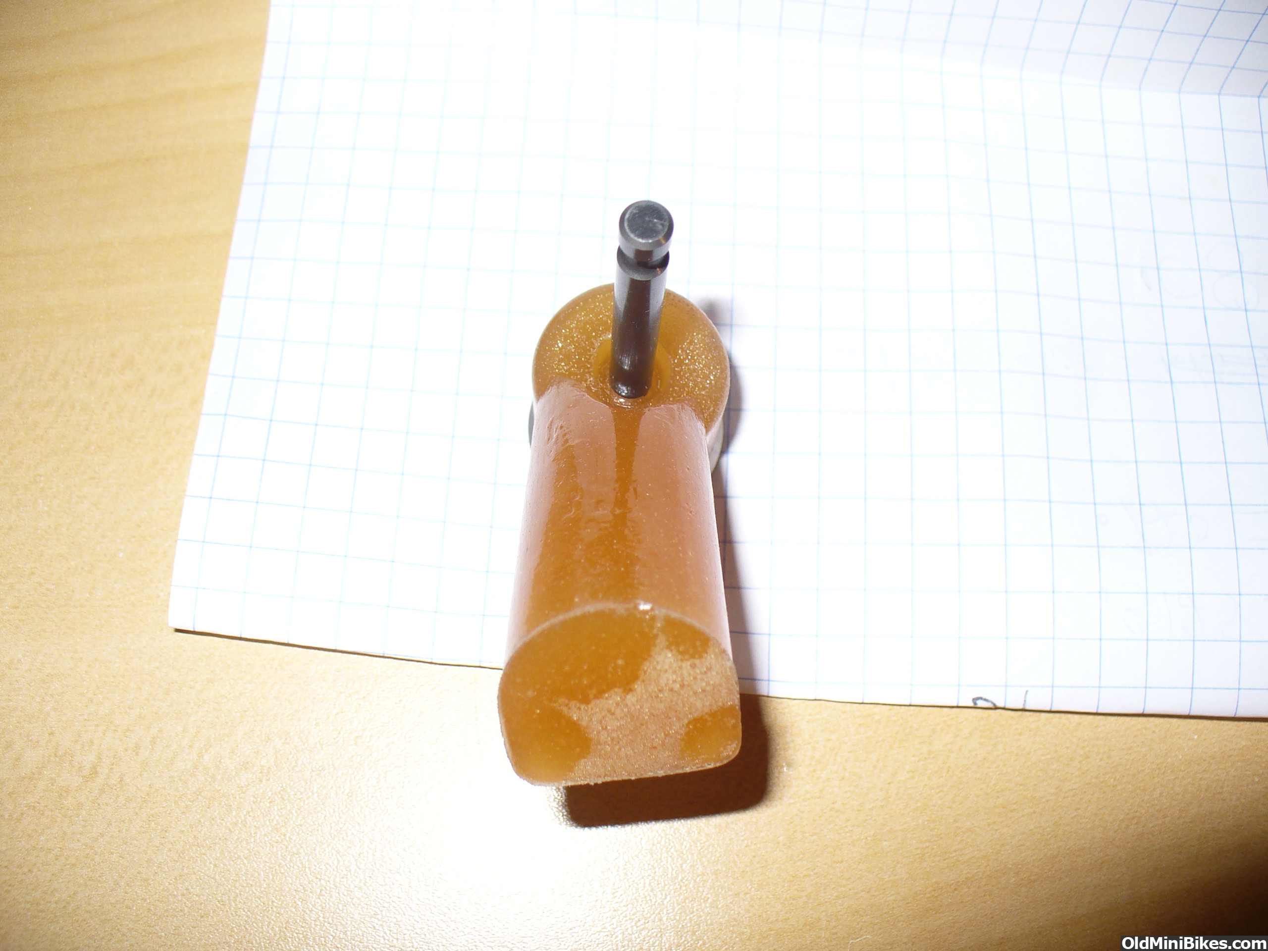
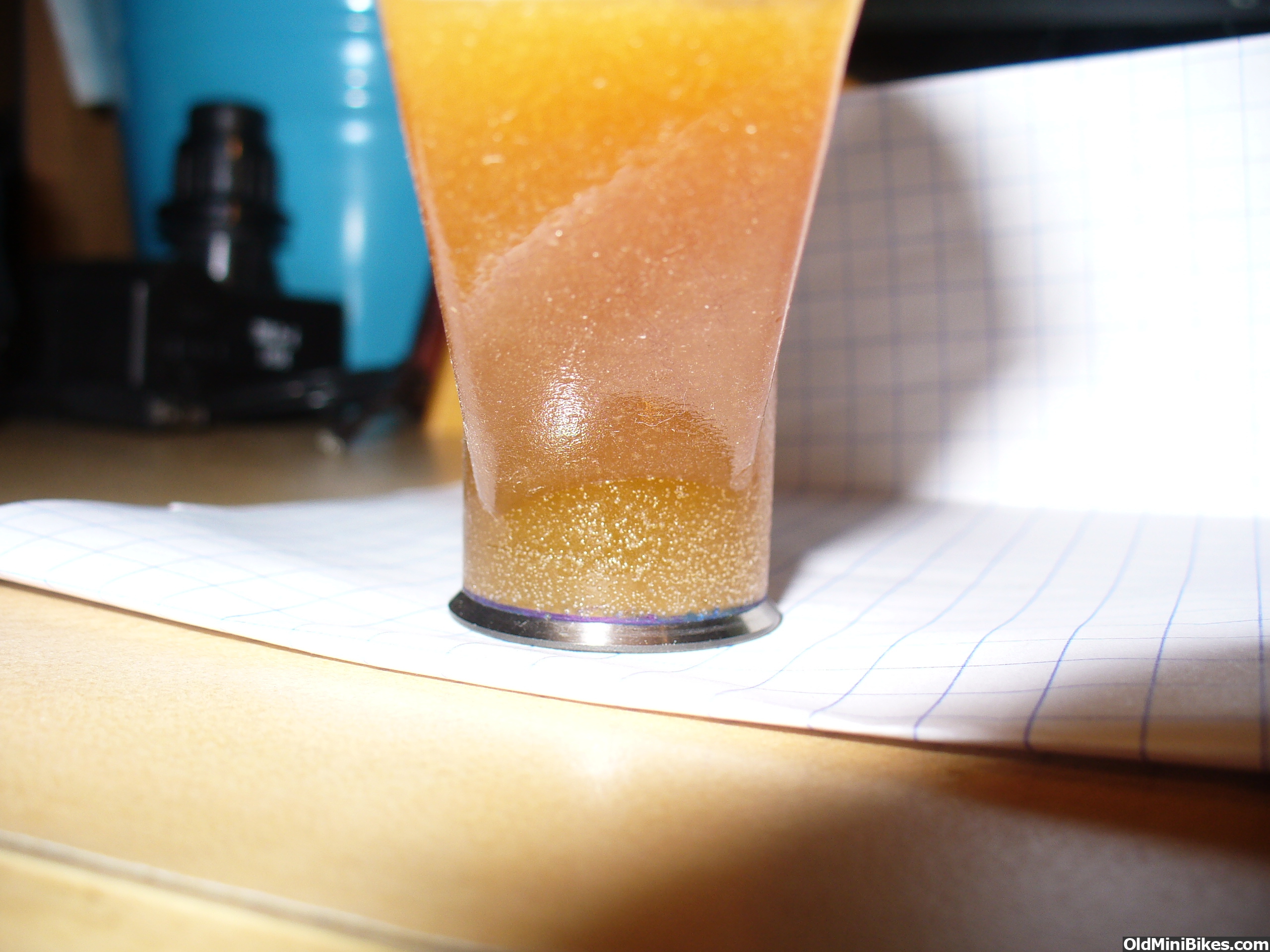
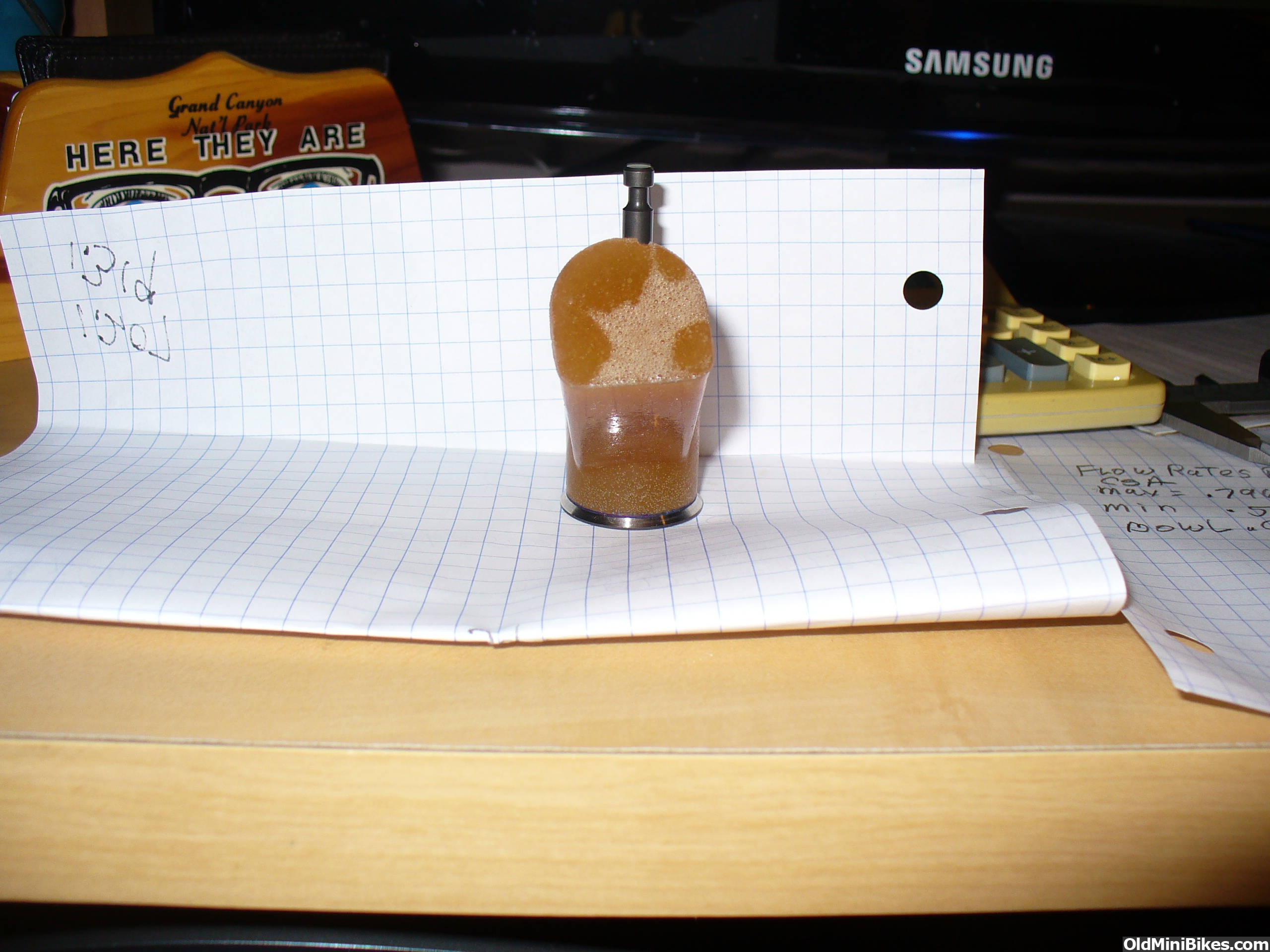
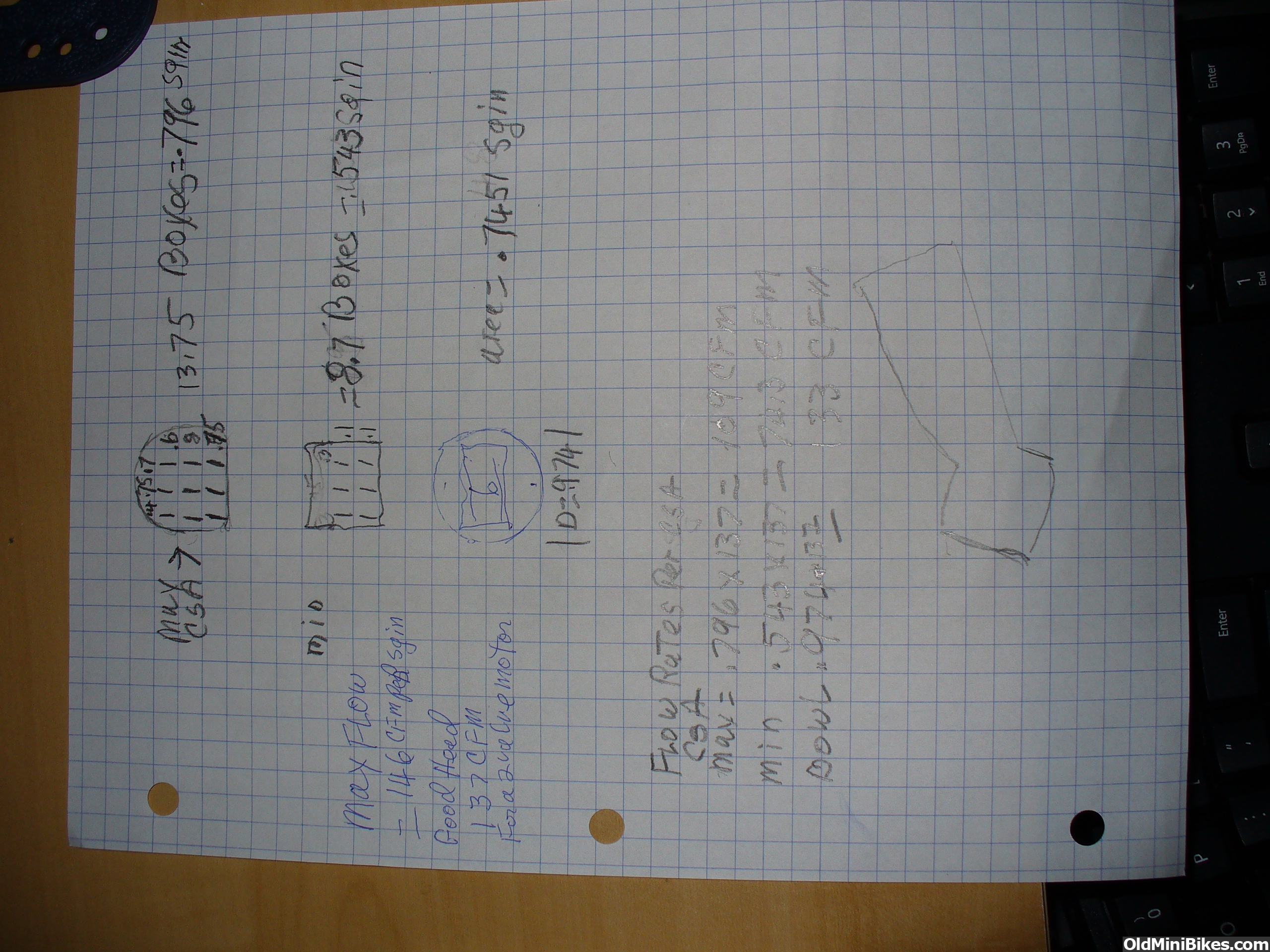
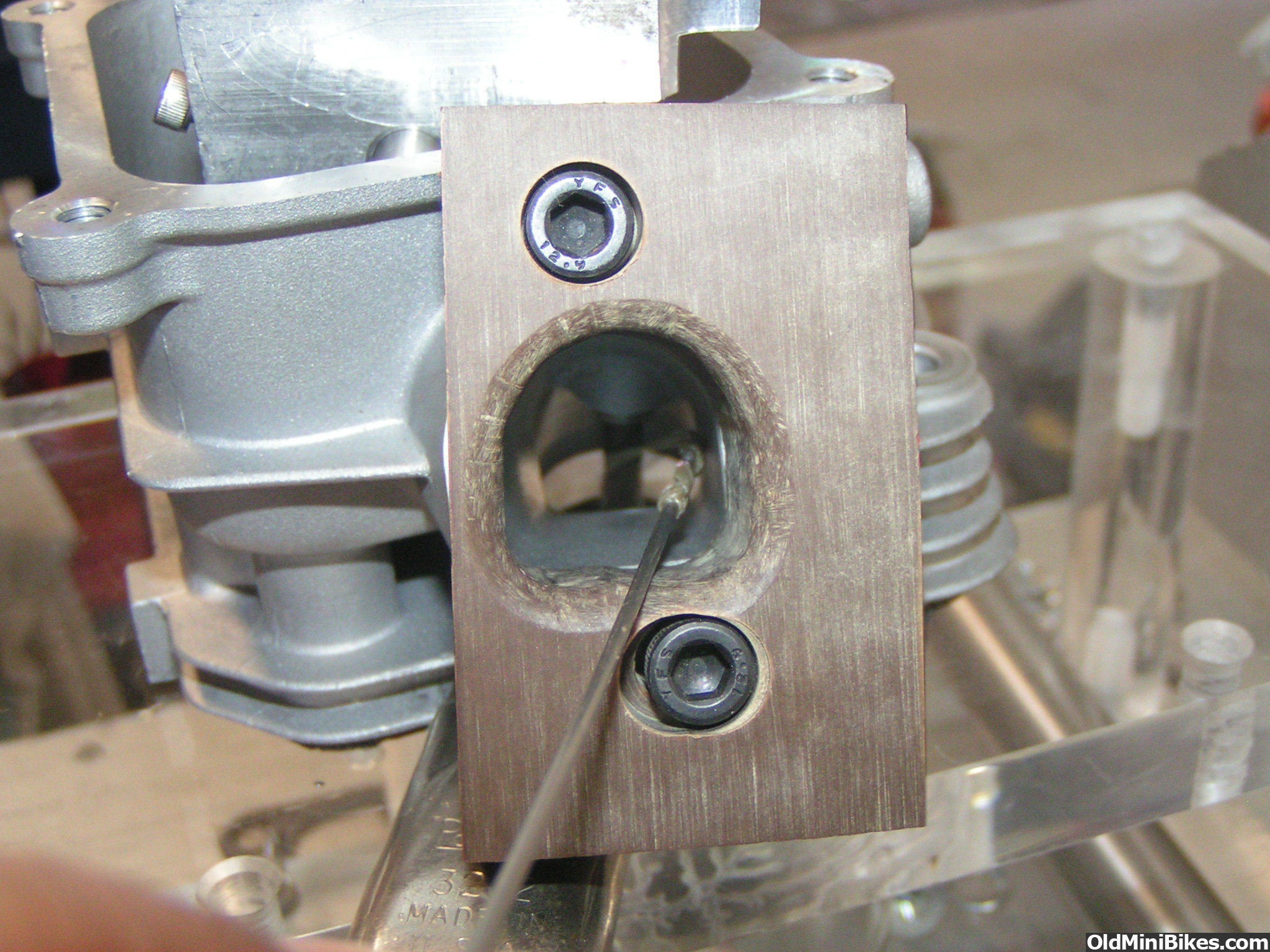
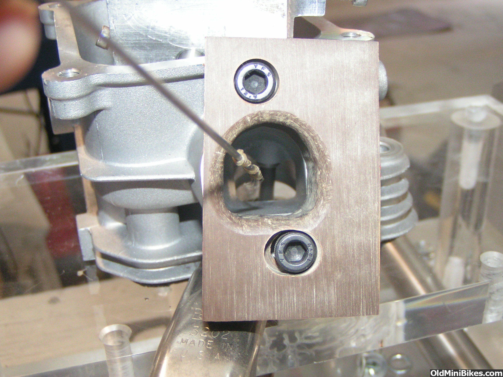
This is my second attempt at building a welded hemi head. (first one I hit the seats welding and lost interest, sent it to race city tools to have a machining fixture made for hemi heads) I took a baseline flow measurement and again noted that the flow is no better than a regular head although the exhaust on this one is pretty good so mods will be mostly to clean up short side and guide area and minimize reversion. The intake seemed to really neck down by the valve bowl so I made a port mold and it is real interesting as the bowl is at a angle to the port and the roof is really collapsed on one side. I see a lot of potential for this head. I took a number of measurements to share and will chart the progress as I go along. The shiny areas of the bowl are sanded down in prep for welding. I want to add two small squish areas to reduce CC's but not try to make another heart shaped chamber like the last one that hit the seats with the arc. I also do not want any shrouding. The max CSA (cross sectional area) of the port is at the beginning and I measured ,8125 Sq inches. Where the port intersects with the bowl is approximately .720 Sq in. It is difficult to measure exactly as one side is shorter than the other. I calculated the max CFM@28" for the max csa at 113 cfm( this assumes a CD of 1 which is a straight pipe and maximum flow possible) and at the smallest CSA is 100CFM (max possible flow for that CSA) . The valve guide bump right where the smallest section is would drop that figure considerably. The bowl is not tapered toward the top like a clone head but is a constant diam of .974. I will be filling the bowl area on the top longside so when I port the roof I can keep a constant radius if possible. When I finish I will take another mold. Hope this writeup is not too confusing as I seemed to be challenged when I have to describe stuff in writing.

 
#7
Well I did more measuring and figuring and my original calculations in the first post was wrong. I am using graph paper with 1/4 inch squares and when I was figuring the area I was dividing by 12 instead of 16. (16 boxes = one square inch). In one of my books it states max airflow per square inch is 146CFM and according to Darin Morgan a good head should have 137CFM per Sq in. I'm sure none of mine come close but I am using that number just to see what the maximum amount of air that would be possible to flow thru the different sections of this port as is. The largest part of the port runner Max CSA (end where carb attaches) is .796 SQ inches. Using the 137CFM number it could flow 109CFM max. The port tapers down to where the bowl is machined to .543 Sq inches which would have a max flow of 74.3 CFM. The Bowl is .974 in diameter and is not tapered is able to flow 102 CFM. The actual port flowed a max of 47.5 CFM. I also took some pictures of the mold so you can see the tilt the runner has going into the bowl which creates a unequal Short side. If you look at how the runner enters the bowl it is offset to the left. I am just guessing here but I bet they designed the hemi without squish to reduce NOX emissions and designed this port for a lot of swirl to compensate. So my plan is to first weld up the chamber with two squish areas, next roughen up and epoxy up the bowl area so I can port the longside and have a nice radius into the bowl as it has a big dead area now. I will port the roof with the guides removed then install the bronze guides I got from Isky, do the valve job using a 85 degree bowl cutter to open up the bowl to adjust for the 28.5 intake valve. then back on the bench to figure out what I will do to the short side. I am figuring to at least fill the bottom of the runner at a angle to raise the low side so I can put a even radius on the short side. I will use clay to mock it up.
 
#8
Great info here , can't wait to see the welding of the chamber . I also have a hemi head laying around and maybe I will learn some tricks here .
 
#9
The port castings you made show a weakness in the G head I noticed a long time ago.

I never made the casting fix but I did carve some inserts to be welded in to the port ( brazed actually with a low temp rod ).

BUT....
I chickened out and never completed the project.
 
#11
I have used epoxy in the past on a few of my mini's and they are still running fine with lots of hours with regular pump gas so once the welding is done I will use epoxy in the port / bowl, don't have enough confidence in my tig weiding to try to tig the longside of the bowl.
 
#12
I decided to test the head stock to see if I could see swirl and how the shortside works. Using string probes the swirl the stock head generates is tremendous. Also with the valve at .350 lift I could not get the string to go around the right side of the port, It was always pulled to the left side where the port is offset to. I took out the valve and plugged up the guide hole and took a quick video of the string spinning around clockwise.


http://vid255.photobucket.com/albums/hh136/ole4/clone head testing/PICT0294_zpsp2fpgkcn.mp4
 
#14
A lot of this is just because I am curious. I also tried to use clay to fill in the top of the bowl on the longside and radius it into the port but Before I could get a reading it sucked the clay into the flowbench. The string also showed the flow around the shortside at high lift was at least a quarter inch away towards the longside. The lack of a radius I think is causing that.
 
#15
I use Devcon WR2 with no failures in ports.
But I really wanted to get something in the exhaust port too.... (so the braze idea was born ).
I melted two heads to get one that looks OK.

Interesting video.
I wonder what it would look like with a valve.

I am still looking at this head, well it mocks me when I lift my head from the Onan BGE that's currently eating all my time up.
 
#17
All in the name of some serious laminar flow. I like it. I'm in the process of designing a head from scratch that I will be manually machining for a Kohler SH265 drag engine.
 
#19
Well I finally got back to working on this, been sidetracked with other projects. I decided not to weld up the chamber as I was worried about losing the interference fit of the valve seats due to the heating of the aluminum when welding which tends to relax the fit of the seats. At least that is what I read on the Brodix site. I just did a quick porting into the bowl and a radius on the short side. I am trying the Bronze guides isky sells on this with the longer valves from SI. I cut the spring seats wider for the 37 LB springs. Just need to open the intake throat with a bowl cutter for the new larger intake valve and cut the seats then back onto the flowbench to see what improvements I get.
 
Top