PAP's - Renegade - (Anything Goes)

#81
Well, I really don't have a "paint booth" so to speak, but I do have a small finishing room that I spray a lot of smaller things such as gun stocks.
But I do have a brother that paints in a body shop....don't worry, I have it covered. I can powder coat the smaller parts, as long as it fits in this
old Kenmore oven.
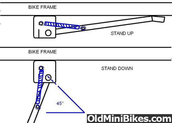
I been spending a hour or 2 every night working on a kick stand, which eventually led to a total re work on the foot peg placement and the brake pedal arrangement. I originally took Dave's advice, and tried to make a kick stand, and the geometry gave me a headache. After several attempts, I went back to the center stand idea, and that's when I figured out the foot pegs weren't in a very comfortable spot.
I moved them ahead about 4" and 2" lower, utilizing the crossbar for a stop for the center stand. So I finally got the center stand fabbed up and the spring geometry conquered, now it's on to re-engineering the brake pedal and linkage.
 
#83
That much I had figured out....what complicated things is the angled motor mount, and the fact this had to tuck up under the driven pulley.
 
#84
Well, this rear brake linkage deal has whipped my ass. After 3 attempts the brakes still suck.


No matter how much leverage I put on them, they wouldn't stop a tricycle. I don't ever recollect drum brakes being this inefficient, but these are simply a @#$%$%^ joke! Maybe I just got a bad example. Now the front brakes.....that's a different story.
I can honest say that I am very shocked and elated the way they work.


Once I got the cable on and tuned out the slack, I rolled across the shop and squeezed the lever, and it was probably a good thing that the floor was dusty. The front tire locked up solid, so I did it again, this time with a clean floor and a clean tire. All I can say is that if road conditions were right, this thing would do a wheel stand or throw you over the handle bars. After that little confidence builder, I made up my mind.....screw the drum brakes! I'm building another disc set-up. So I just happened to find another saw blade and enough aluminum to make a rotor mount.

Now it's back to making another caliper.
 
#85
Well, this rear brake linkage deal has whipped my ass. After 3 attempts the brakes still suck.


No matter how much leverage I put on them, they wouldn't stop a tricycle. I don't ever recollect drum brakes being this inefficient, but these are simply a @#$%$%^ joke!
The lower/shorter you hook up the rod to the front lever (the black/silver one) the less pressure and more movement it will take on the brake foot pedal. The longer you make the lever on the rear wheel the less pressure and more movement it will take.
Your work looks good so far, nice.
 
#87
Made a little more headway on the brake caliper. This might give you an idea how this works. Instead of plungers pushing against the brake pad, I utilized 5/8" ball bearings. The actuator lever also has a bearing around the center shaft.

The anchor for the cable is mounted on the caliper for less distortion when pulled.
After your statement about how violent the front brake reacts I think you could help it function better and have more gradual application if you were to machine a ramp on the sides of the holes the ball bearings are in on the lever side. The piece that is loose and laying on the rotor. The ramps would allow for a much more controllable/gradual application of the pressure created buy pulling the lever upward. It wouldn't take a long ramp or an aggressive angle. The way it is now, it looks like the balls are being pushed out of the hole at a 90 degree angle where a 45 or 60 degree angle might be better. :shrug:

Doug
 
Last edited:
#88
I wasn't meaning to imply that they were"violent", just effective. But I know what you are saying. I have learned in the past that a more gradual ramp leads to sticking because of a wedging effect, and it takes one hell of a return spring to unlock them.

{The lower/shorter you hook up the rod to the front lever (the black/silver one) the less pressure and more movement it will take on the brake foot pedal. The longer you make the lever on the rear wheel the less pressure and more movement it will take.
Your work looks good so far, nice. }
I tried several leverage ratios, and it wouldn't lock the brakes up no matter what. It's has to be in the brakes them selves....I think the shoes are undersize for the drum, not providing enough surface area. Makes no difference at this point, I've got a better idea.
 
#89
I wasn't meaning to imply that they were"violent", just effective. But I know what you are saying. I have learned in the past that a more gradual ramp leads to sticking because of a wedging effect, and it takes one hell of a return spring to unlock them.
I didn't think about the ramp effecting return. That makes since to me though. Oh well, it seemed like a good idea at the time......

Doug
 
Last edited:
#90
Since I slipped off the first page, I figured it was time for an update. Despite the fact that I caught some nasty bug last week that knocked my dick in the dirt, I still made a little progress. I started on the rear brake caliper after I lucked into some chunks of billet hidden away in the scrap pile.

I just looks like a scrap sammich at this point, but I have all the critical holes drilled and tapped.

I then proceeded to work from the inside out.


I'm currently working on the actuator arm and should have it done by this weekend.
 
#91
Pap I just dont know how you guys do it!! I have trouble getting my tv on the right channel let alone programming and measuring "correctly" to ever be able to do something like that!! I do love to see it though!! :thumbsup:
 
Last edited:
#92
Pap I just dont know how you guys do it!! I have trouble getting my tv on the right channel let alone programming and measuring "correctly" to ever be able to something like that!! I do love to see it though!! :thumbsup:
Late nights, lots of coffee and inspiration from the guys here.....:thumbsup:
 
#95
I happened to be in the local auto supply getting some acetylene, and picked up some oddball,dust collecting brake pads for cheap. With some trimming, I fit them to the pockets like they belonged there....that was the biggest hold up and now the caliper is finished.


I couldn't wait to get it on, and once I did, I discovered one hell of a wobble in the rotor. This thing was wavering back and forth about a 1/16" . The rotor was true, the mount hub is true, the problem was actually in the wheel itself. If you are not familiar with these wheels, they are a little different from normal. They are comprised of 2 sides, a rigid side, with the spindle hub welded to the wheel half, and the other side that just floats around the hub. The are bolted together with 8 bolts, in a large circle towards the outside of the wheel.
The rigid side is the side that the sprocket mounts to, and it runs fairly true. The other side (which the rotor is mounted to ) has some distortion from the extreme o.d.(where the bolts hold it together) and the smaller surface where the rotor hub bolts on.


I can't live with that much wobble, so I came up with a few options. 1. True up the mounting surface of the wheel on my lathe. 2. Insert some shims between the hub and the wheel. 3. Index the wheel halves, hoping that both were distorted and one may cancel out the other.
When I checked the run out with an indicator at the bolt hole diameter of the rotor hub, it was .020". I wasn't crazy about trimming that much off the wheel to true it up. Turning something of that size and nature almost always results in chatter and makes the problem worse.
I started to make some shims, then realized that was going to be a pain in the ass because the hub was bolted to the wheel from the opposite side and nearly impossible to get to the bolts without splitting the wheel. Time for option 3. I marked the hub at the 4 points of attachment with the run out, then made an index mark on both halves of the wheel. I split the wheels and turned the floating side 180 degrees clockwise. Checked with the indicator and basically got a mirror image effect in the opposite direction. This told me that both sides were distorted and this just happened to be "worst combination" scenario. Eight bolts mean that there are 8 different combinations, so it was not going to be that hard to find one that is better. After about 5 tries, I hit a good spot at 90 degrees clockwise. After I bolted it all together and put the rotor on, I was absolutely shocked when I checked the outer surface of the rotor with the indicator.....only .003" run out!!!
So I would never have to go through this again, I drilled an index hole next to the valv stem hole.

I must say, I think the rear brakes work better than the front, and the front worked well!

Wow...glad I got that licked. Then of course I find another little annoying issue. As I rolled the wheel checking run out, I hear this little tick,tick,tick...alright, NOW WHAT?
Seems that the valve stem is just barely hitting the back of the caliper.


I know what this will do at high speed, so I made a clip from some brass shim stock to pull it closer to the wheel and give more clearance.


I feel like I've accomplished a milestone. So far: It rolls, it stands on it's own, it has plenty of "whoa", now it time to work on the "go".
 
#97
I just realized I forgot the big picture.


There's definitely something in Delphos' water supply......I'm smart enough not to drink it.
 
#98
My first-ever build used these wheels. Nothing near as complex as what you've got going on, but I had to come up with a way to space the sprocket out from the wheel flange. I used an aftermarket Ford fan pulley extension and had to correct for run out also. All trial and error as you just showed! :thumbsup:
 
Details, details, the devil is in the details. Once I re-positioned the carburetor to be level,(going with a slant motor mount) it was obvious that that I would have to completely re-engineer the linkage. The plastic throttle stop had me scratching my head, so I made one from 1/16" steel.
The plastic version came off easily with a drift, and it not only has flats, it has a groove that the plastic was molded around. This came in handy for attaching the plate. I filed out the shaft hole to mate with the flats, then used a "C" clip to retain it. Once I had the bends right for the WOT stop and idle adj, I had to figure where to drill the hole for the wire link. The whole system needed to be supported by another bracket for the cable attachment and bell crank. Without beating my head against the wall figuring all the weird bends, I made a paper template mock up, then flattened it back out to use for a pattern. Once I got the basic fit, I trimmed the rest. Somewhere in the middle I needed another lever to transfer motion from the cable to the butterfly, so I came up with this "cross legged" bell crank that uses a torsion spring for return.


With that out of the way I started on a breather. Drinking lots of coffee sometimes fuels brainstorms. I found an old stainless steel coffee mug and a stainless thermos cup that just fit over the filter. I cut the bottom from the mug and made an adapter to bolt to the carb.


I got it fitting quite nicely, but the the choke lever just wasn't going to cut it. It not only would not stay on place, it was just cheesy looking. I found a solution by turning up a knob from aluminum and attaching it by drilling and tapping the post that it rides on and securing it with a 6-32 screw.

A click to the right turns the choke on, and it is slim and non intrusive.
 
Last edited:
Top