1946 Doodle Bug [Hiawatha...not the China Junk]

#21
from OldMiniBikes member tooljac

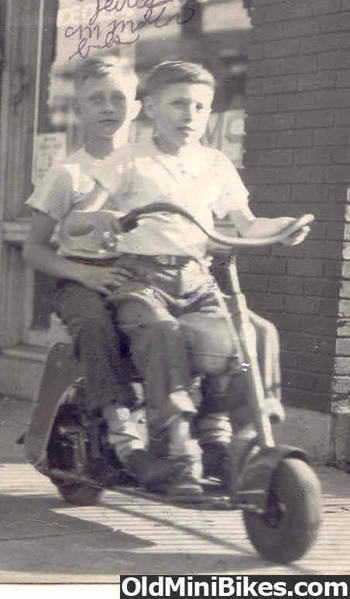
This is an original picture from Jack Spitler of him and his brother:


Jack Spitler: "This is a picture of What I now believe to be about the first minibike produced, Im driving and my brother is on the back, Was called a Doodle Bug sold by Western Auto, Our Dad bought this for us when I was 12 years old which would have been in 1946 Im 72 now and still have minibike's."


.
......
 

Oldsalt

Well-Known Member
#23
That front plate is cool as hell...I added it to the Fork Plate/Badge thread thanks :thumbsup:

that was a clever way to pop those pins...they can be a s.o.b. to get out without hurting or scratching the plate.
Sometimes when restoring an old piece of machinery there is no way to get at the backside of them and you have to ever so carefully file the top flat, center punch/drill them out........:thumbsup:
Never tried that method but I can see that it would work quite well. The other more tedious method I use to remove a drive rivet is to carefully cut a slot in the head of the rivet using a very small jeweler's file. I got some cheap ones from Harbor Freight that work OK. The 'serrations' on the shank of drive rivets are spiraled in the same direction as regular right hand bolt threads. Carefully insert a little screwdriver [specially ground for the job if necessary] and 'unscrew' the rivet. [Righty-Tighty, Lefty-Loosey]. You might try this method on a 'blind' rivet that can't be got to on the back side, if it doesn't work file and drill like you pointed out.
 

Oldsalt

Well-Known Member
#24
Real lucky that the floor pan was only introduced to the curb one time. However, that was probably what made the entire piece come loose. In the dim past someone tried to arc weld it back on, they just burned some holes. Failing that they pulled out the acet. torch and brazed it back on. That caused a bit of warpage. I cut the braze welds with a thin blade in a small right angle grinder and did the body work. It is now acceptable to put back on because the small bad spots will be covered by the rubber covering. OK, maybe it will require a little putty and sanding but it will be just fine for anything but a show machine. This bike is going to be ridden on the street.
 

Oldsalt

Well-Known Member
#26
Today decided to make the parts for a drive guard. A guy sent me patterns. The 1st pic shows the patterns and some metal I had sheared to make two guards. The slots could be cut using other methods but as a mill is available that is what is used.

In the next picture a piece of sheet metal, to make a cover, is in my little mill. Its clamped down on a piece of plyboard. There are scribe lines and 1/4" holes at the ends of each slot.

Next, a 3/8" slot is being cut using a 3/8" end mill. The last two pics show the 'wrap-a-round' piece and the cover with its three slots cut. Notice that the pattern for the cover, which is for a model built after 46, shows three slots. As my machine is a 46 it is suppose to have five slots. Using a picture of a early guard I replicated [as close as I could] the five slot layout.
 

Oldsalt

Well-Known Member
#28
Now that the drive guard parts have the proper slots they were formed. The first picture is the Harbor Freight dies in a bench vice. They have magnets and stay in place. I don't see how anyone could get along without these 10 buck dies if they make small parts for minibikes. Sure, I could wait a day then take the part to a local fab shop, wait another day or so and then pay MONEY. The next pic is the completed 90 degree bends. Just took a couple of minutes to do. The next shows the wrap-a-round piece having its radius formed to match the cover. Two pieces of pipe welded to a piece of scrap angle does a super job...IF you take little bites and go just a little at a time. Then the pieces were tack welded together and the nose sanded. See last pic. Looks like it's good enough for the women I run around with.

I am guessing the patterns I received are right, guessing at the spacing and length of the slots, guessing about how they were originally welded together. After the side panels and engine are trial installed I'll know if the pattern was correct as far as length of the guard. I left it long for now. Also, at that time, I'll know how to attach the brackets....maybe. I have patterns but have never seen a guard other than pictures and both are not enough information.
 
Last edited:

Oldsalt

Well-Known Member
#30
The ext item, it seemed to me, was the side panels. I was sent, by three different kind people, patterns for them. All three were different. The three were 'averaged' and the final cardboard pattern is shown on a piece of 16 ga. cold roll sheet. I have no idea what gauge was originally used but 16 seems about right for the application. The parts were scribed and cut out with a 'Beverly' shear that is capable of making inside and outside radius's. As the sheared edge is slightly deformed the pieces were cut about 1/8" outside the scribe mark and then sanded to the scribe mark. The next pic shows the trusty fixture used to hand form metal to a radius. The last pic is a side panel mounted on the frame. In the lower right it can be seen that there is an alternate layout. As these side panels are for an early they were supplied with the 'hoof' projection out the back. The nearby line is for later model Doodle Bugs. The hoof was eliminated. Probably good riddance. But I'll use it
 
#32
Very nice! Now you need some black, round head standard slot screws to attach it to the frame with :) My right hand guard (as I sit on the bike) has a 1" or so slot in it at the top just next to the where the main crossbar T's into the seat part of the frame. I believe this is for the brake cable and the cable goes under the bar, I think with the earlier one cable type the cable went through the bar, is there a hole there ?
 

Oldsalt

Well-Known Member
#33
Very nice! Now you need some black, round head standard slot screws to attach it to the frame with :) My right hand guard (as I sit on the bike) has a 1" or so slot in it at the top just next to the where the main crossbar T's into the seat part of the frame. I believe this is for the brake cable and the cable goes under the bar, I think with the earlier one cable type the cable went through the bar, is there a hole there ?
Yes, there is a hole in the 1" tube for the brake cable to go through on this early model. The side panel has a vertical slot at that position so it can be removed without withdrawing the brake cable. This was shown on the side panel pattern [that I was sent] that was for the early style.

After working with the pieces I have come to the conclusion that the side panels and the fancy-smancy drive guard and design afterthoughts. It is clear to me that the frame/engine/drives/wheels design was worked out and then their eye fell to making it a true 'scooter' with a 'look' that was 'modern' and stylish. Take a look at the Salsburys and Moto Scoots and common Cushman and etc.. They all HAD to have body panels to be accepted as a 'scooter'. A full front fender was common before and after the war. Again, I believe the styling issues came last and were 'stick-on' items....except for that cute little front fender! The "hoof", only on the early model that sticks out the rear of the side panels, to me at least, denotes an attempt, a last minute attempt, to show a 'swoopy' appearance that denoted speed or motion. They got rid of that soon enough. I can but imagine droves of people asking why it was there and no one having an answer. I trust I'll incur the wrath of few if I opine that the body work, with the exception of that lovely and well proportioned front fender, is terribly amateuristic and quaint. And, in that opinion, I'm being kind; many would use really jestful words. The seat, again...this is just but one man's opinion, is the epitome of afterthought design. Lights, license plate mount, on-off switch, fuel tank and it's mounting all show a rush to market that can't be described, except by a very, very charitable person, as being well thought out.

I suppose today is a good day to do a trial fit of the engine and think about what I'm going to use as a drive system. This is where I must stray far from original. I do not have the correct engine...no kick starter. There are no original drive components or rear wheel and axle. All must be special made. There is absolutely no chance I will search around and pay big bucks for those parts. It's simply not going to happen. As the original drive system was of a crazy and complicated design it will not be replicated. The attached picture is what Yesterday's Rides sells as a modern version of the Doodle Bug. As I have some late model engines that are nice [5 HP Briggs] I still have it in my mine that it's an option. With the TAV it would be a nice runner. I can buy a TAV from OldMiniBikes for far less than an original clutch. As my machine is to be ridden on the street it does make sense. The second pic is of the owner loading the jig he made for perfectly replicating the frames.
 
Last edited:

Oldsalt

Well-Known Member
#35
Well, seemed like it was time to check out the engine. The guy that gave me the engine years ago took it of a Planet Jr. garden tractor that his father bought after the Second World War. It runs quite well. However it has a different bolt pattern than the engines used on these machines. New holes could be drilled in the engine plate to accommodate the engine but that seems like a poor choice. I drilled the engine to match the Doodle Bug. The heavy radius on the cast motor base had to be removed so allow the mounting bolts to sit flat. A end mill took care of that. See pics. The engine is a collector engine but it is better to deface it's detachable base than to start drilling new holes on the engine plate. With this done the big job of determining what is to be used in the drive and clutch system.
 

Oldsalt

Well-Known Member
#36
Re-assembled and trial installed the engine. The effort was to get the drive guard installed using the patterns for the brackets and the pics marc1959 posted. It was not as bad as I had envisioned. The pic shows the guard installed.

Now the drive system can be started. That I'm sure will be the most involved task in the project. As previously stated, this is not a restoration. It would take a long time and a lot of money to buy the few original parts still available. So the clutch wont be an oil filled unit it will be a Max Torque from OldMiniBikes. The primary drive will not be by belt...it'll be #35 chain. The jack shaft assembly will not be of aluminum castings. I'll build a steel weldment that echos the original design. The rear wheel hub and sprocket assembly will also have to be hand made.
 

Oldsalt

Well-Known Member
#39
Started making parts for the jack shaft. The jack shaft on Hiawathas sits at the top of an arm that pivots around, and is mounted to, the rear axle. The original is made of a couple of aluminum castings. To find an original set-up would take time and be costly. So from pictures I'm making one out of steel. The 1st pic is a couple of parts being welded. The next shows the weldment partly completed. The machine work on the end that fits on the axle is complete. The round piece at the top will be bored to accept a couple of 5/8 ID bearings for the actual jack shaft. The last is the weldment in place on the bike. The two bolts in the slots will allow the chain that drives the wheel to be adjusted for tension. This is certainly not how it was originally done but almost none of this assembly can be seen. And I firmly doubt this machine [here in Walla Walla] will ever be seen by anyone that knows it is an ersatz part. Anyways, it will be pained Okie Chrome so it might pass as aluminum.
 

Oldsalt

Well-Known Member
#40
The drive system is just about finished. I ordered a couple of special plate sprockets from McMaster-Carr that OldMiniBikes doesn't carry. They'll need machining and welding. Should be here this week. The pics shows the side view looks sorta stock. Close enough for the folks on my block. The view from the rear shows the primary chain adjustment screw is done. Next is to make the sprocket adapter for the rear wheel then the jack shaft.
 
Top