Cloning a Lighted Tec H-50 minibike motor "How To"

#1
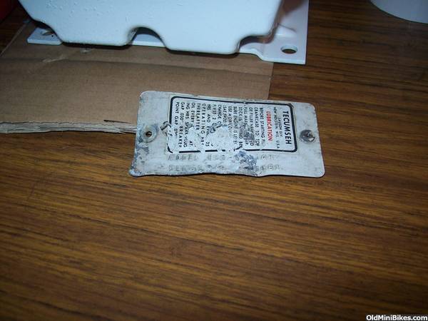
First you're gonna need a Tec big block.. In this case we have a VERY LOW hours HM50 big block.. HM being the iron bore aluminum block, it will look all the same, but have a hidden iron cylinder..

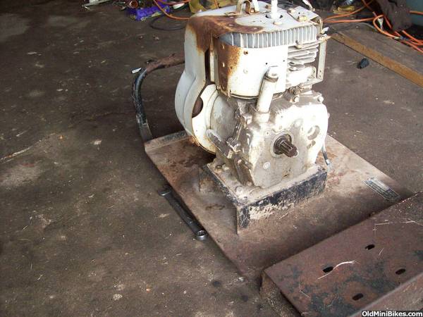
When I received the motor it had been a salvaged power sprayer. Kevinheimer got it from his dad who bought it new years ago, used it once, then it sat forever.. Eventually Kevinheimer and Doug robbed some parts for some project they had came across.. It sat for some more years before I found it..

Needs a crank and some gussying up but the base is nice.. Low miles, not smashed in half from the junkyard, what more can ya want?? :shrug:


#4
Uhhhhhhh... Let's see.. I want a 1969 Rupp Goat engine.. Which wouldn't be lighted, but bike is lighted and horned and stuff... So really I need a 68 TT500 engine, badged 69.. :shrug: So... we're gonna need ..


#1 a crank :glare:

#2 ball bearing case cover, with short dipstick

#3 carb and intake

#4 minibike air filter

#5 lighted aluminum H or VH 40-70 flywheel

#6 three prong plug lighting coil

#7 recoil housing.. All minibike motors have a strait up pull rope, and TT500 / Goat
supplies it's own tank, therefore the cover will need no fuel line holes
+ throttle assembly


#8 throttle assembly itself.. :doah:

#9 69 H50 aluminum tag... :facepalm:

#10 paint

#11 stickers

is that all ??? :laugh:
 
#5
I'm mostly concerned with the lighted parts. I'm building his and hers Trail Blazers. The both have H series big blocks from snow blowers. I'd love to make them lighted.
 
#6
Well, no pic of the crank I guess.. :laugh: OR the air filter.. I managed to trade a regular round one, for a minibike correct one that was on a guys Italian rototiller.. :confused: 
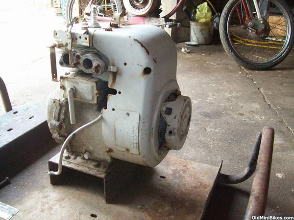
Lighting coil and flywheel have been around for a while.. Carb is a carb, had or made one of those with all the right parts..

GONNA need a cover... :facepalm: I had a a gray one with NO options, and the pull rope holes oriented on the 90 degrees.. It had numbers stamped into the top, but enough primer will cover that up... Otherwise :shrug: All we need are the holes and parts..

So, I used the holes on my Goat motor for reference.. :hammer:

To get an accurate measurement and layout.. I am gonna need a strait line X-Y axis and a zero point.. The lines need to sit dead plum to the earth as all the rest of the measurements from the original blue print would have been..

I have noticed if using the edge of the bottom area back side of the shroud, that tends to very square to the rest of the cover. Like all the way around the bottom of the shroud will sit nice and flat and square on the ground, if it weren't for the raised area around the head.. I was able to make the cover lay flat on top of a small level, and that made a nice squared off strait line, which was wide enough to keep the cover leveled off square to world and the entire operation... :hammer:

I have also noticed, the small half oval notch near the bottom throttle piece, is always cut like dead nuts square to the shroud and motor and world, so I will use the bottom line of this notch as my zero line for the vertical measurements.. :hammer:

From THERE we are able to start finding some height width with the calipers..

 
#9
Here's a pic of the lines I have scribed onto the black shroud, so I had lines to measure from to transfer X-Y measurements into hole points..

I used a hacksaw blade (smooth side) as a strait line, as they are very strait, and will curve to fit the convex of the shroud... Basically lay flat on a rounded surface, yet remain a strait line to follow.. With the hacksaw blade pinched tight to the cover it was as easy as scrape a line in the paint with a knife tip...

Here's my holes and messed up tag and throttle stuff.. I had better pics of the TOTALLY DESTROYED 1970 H50 tag and throttle stuff before I straitened them out.. That stuff was horrible.. I had to RE-STAMP the numbers on the tag with a screwdriver, after hammering the tag back FLAT first.. It was BAD.. :facepalm:

 
#11
Crank cover

ANOTHER problem we have is no ball bearing H50 crank.. I have H60 crank but no brand new H60 rod so why bother??

SO, the only way to know there is no bearing is there are no two keepers that keep the bearing in place.. That's hidden under the clutch so.. :shrug:

All ya REALLY gotta do is replace the long dipstick tube with a stubby.... You can't just yank out the tube, as there are no threads for the oil plug.. It's just pressed in there.. :shrug:

SO.. I'm chopping threads off from a briggs cover and whittlin it down to the right round, to press into place.. :grind:


#12
Tada!!!

A little tapping and super epoxy and we have a threaded hole for a dipstick...

Some paint and reassembly...

a shiny new rope..

Wow.. just like that, only takes three minutes...

On TV.. :lol:


#15
Maybe I should send you my engines. You make them light ready and send me a bill. I'm lazy :)
I'm motivated though as the lovely Mrs Minibikin will be at Windber with me so we need to do some night riding....on bikes :)
 
#16
All ya gotta have is the right flywheel for your motor, and a coil.. lighting coil is a lighting coil for the most part, the flywheel is the hard part.. Your crank taper has to work out, and I think there's about 3 for the big blocks..

there's the minibike aluminum flywheel, also found in some snowblowers and what not.. John Deere riding mower vert motors..

then there's the iron one from the HH60 iron block engines,

And then the same flywheel, with a bigger taper, from the newer engines with points cam built right into the crank..

if you had a newer flywheel with plastic fins, there's a good chance it is round inside, and you could glue in some extra magnets like I did on the Cinderella HS50.. :shrug:
 

gbones

New Member
#17
nice job B:thumbsup: once again a very detailed thread:thumbsup: kevinheimer:laugh: but 1 question, from the finished pics it doesnt look like there is a intake. does the carb bolt rite to the block:shrug: remember im dumb
 
#18
No there is an intake manifold.. They are about 3/8 inch long plate with two bolt patterns.. one is strait accross from each other with two special screws bolted in from the back :facepalm: for the carb, then another pattern on like 45 degree angle, that bolts the intake to the motor with.. Bolt the carb to the intake, screw the intake to the motor...

screws rust a tiny bit, gotta saw the intake in half to save the carb.. :facepalm:

ALLLLLLLLLWAYYYYYYYYYYYYSSSSS when putting together an H, make sure BOTH carb screws and nuts are near perfect shape, and perfectly clean, spins on perfectly perfect.. :mellow: THAT WAY you can get your carb back off without taking off the intake.. Just shove the carb sideways and bind the bolts up to keep them from spinning.... :anon.sml:

Yes, the dreaded H40 intake manifold... NOT one of Lausons better ideas.. :doah:

the very first post actually shows the original intake still on the long block before I started
 

gbones

New Member
#19
ok, i see it now in the 1st set of pics:thumbsup: alright a new question, "why is this intake straight and short, and the smaller tecs have the curved intake?"
 
Top